


Table of Contents Show
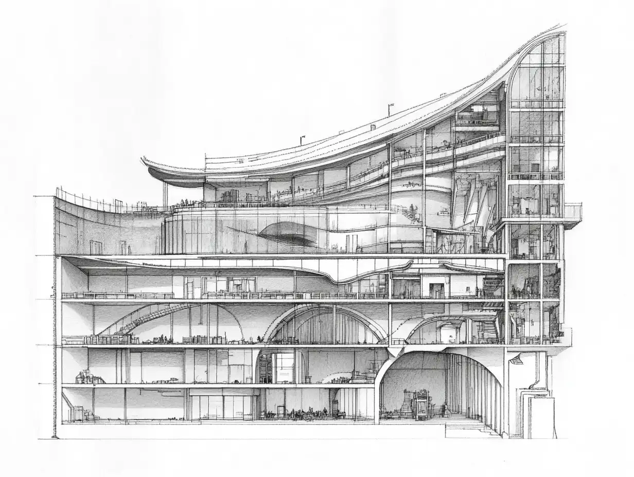
A section drawing shows a building as if a vertical plane had sliced straight through it and the part in front of the plane had been lifted away. A floor plan is the same idea turned on its side: a horizontal cut, conventionally taken about 4 feet (1.2 m) above the floor. The section is the drawing where floor to floor heights, stair runs, roof pitches, foundations and the build up of walls and slabs all become readable at once.
This guide covers how a section is marked on the plan, how elements cut by the plane are told apart from elements seen beyond it, the line weights and poché that make that difference visible, the scales sections are drawn at, and the section types you will meet in a drawing set.

Importance Of Understanding Section Drawings
A section answers questions that no plan can. It is where the vertical dimension of a design is checked, drawn and communicated.
- Visual Clarity: A section shows floor to floor and floor to ceiling heights, double height spaces, mezzanines and split levels, and how a stair climbs from one level to the next. None of this is visible in a plan.
- Construction Insights: The cut exposes the build up of each assembly: slab thickness, wall layers, roof structure and insulation, and the way the foundation meets the ground. At 1:20 (roughly 1/2 in = 1 ft) a wall section shows every material layer separately.
- Design Evaluation: A section shows how tall a room is relative to its depth, how far daylight from a window or rooflight can reach into the plan, and where a ceiling drops to make room for beams or ductwork.
- Technical Communication: Structure, services and architecture meet in section. Beam depths, ceiling voids for ducts and pipes, and roof and drainage falls are coordinated here before they clash on site.
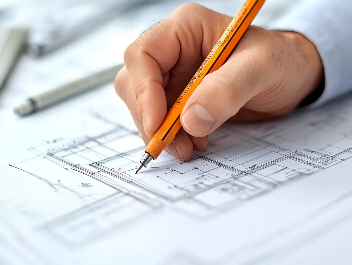
- Educational Tool: Drawing a section by hand forces a student to decide what is cut and what is only seen, which is one of the fastest ways to understand how a building is actually put together.
- Regulatory Compliance: Plan reviewers use building sections to check overall height, stair rise and headroom, guard heights, and fire separation between floors, which is why permit sets normally include at least one section through the building.
In a drawing set, plans say where things are, elevations say what the outside looks like, and sections say how the pieces stack. Many questions on site are vertical ones, which is why sections and wall sections carry so much of the construction information.
Types Of Section Drawings
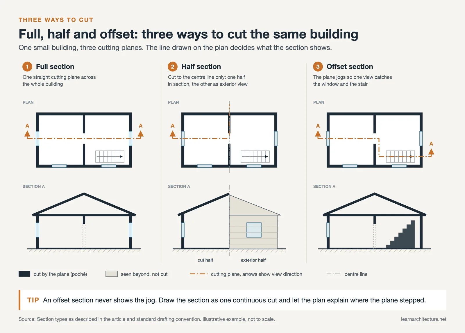
Three section types cover most architectural and engineering drawings. They differ in how the cutting plane runs through the object, and in every case the cutting plane is marked on the plan first, so the section can be traced back to where it was taken.


Full Section Drawings
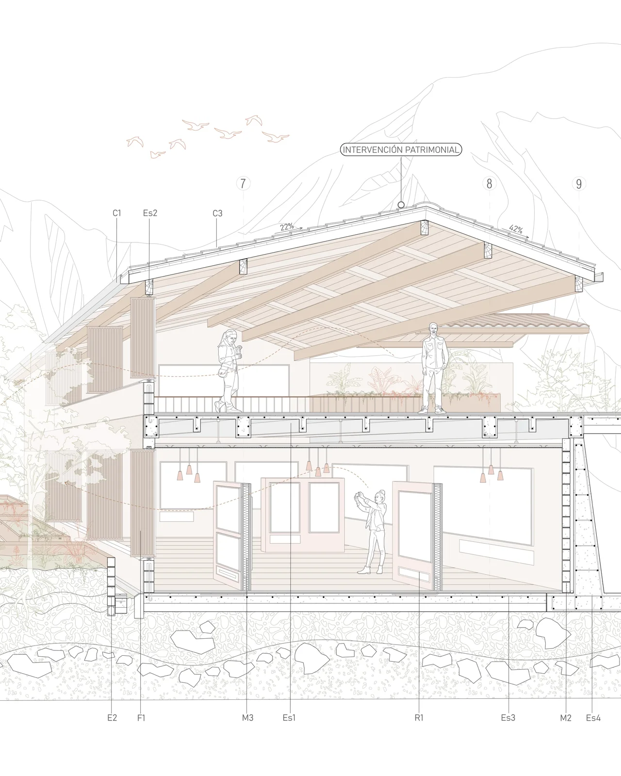
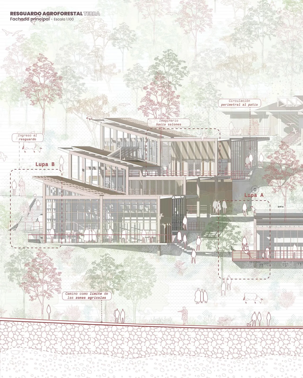
A full section runs one continuous, straight cutting plane across the entire building, either the long way (a longitudinal section) or the short way (a transverse or cross section). The position of the cut is a design decision: it should pass through the most informative spaces, such as the stair, a double height room, a change in roof level or a large opening in the facade, because a cut through a blank wall and a closet explains very little. Drawing sets usually include at least two building sections at right angles to each other, drawn at 1:100 or 1:50 (1/8 in or 1/4 in = 1 ft).
Half Section Drawings
Half section drawings come from mechanical drafting and suit symmetrical objects. The cutting plane passes only halfway through, so a quarter of the object is removed: one half of the view shows the interior in section and the other half shows the exterior, with a centerline dividing the two. In architecture they appear mainly for symmetrical elements such as columns, domes, towers, or fountains, where a single drawing can show both the outer profile and the inner construction. For furniture layouts and room relationships, a full section or a plan is the right drawing.
Offset Section Drawings
An offset section uses a cutting plane that steps at right angles so it can pass through features that do not line up, for example a stair in one bay and an atrium in the next. The steps show on the plan as turns in the cutting plane line, but the section itself is drawn as if the cut were one flat plane: the jogs are not drawn as lines in the section view. Use an offset cut when a straight line would miss one of the elements the drawing has to explain. If the cut needs more than two or three steps, two separate sections are usually clearer.
Techniques For Reading Section Drawings
Reading a section starts on the plan, not on the section sheet. Find the cutting plane line, note which way its arrows point, then separate what the plane cuts from what lies beyond it. The two subsections below follow that order.

Visualizing The 3D Structure
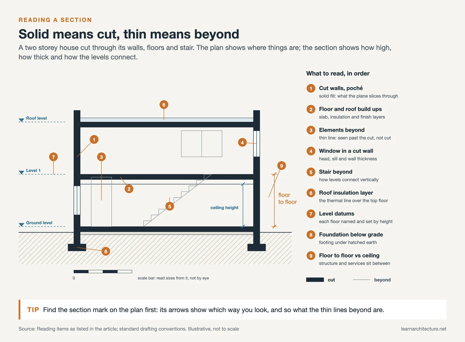
Start with the section mark on the plan. The cutting plane is drawn as a heavy chain line (a long dash followed by one or two short dashes) across the building, with a symbol at each end. The arrows, or the pointed side of the symbol, show the direction you are looking, and the label, typically a letter or number over a sheet number such as 1 over A-301, tells you where the section is drawn. With the viewing direction fixed, read the section level by level from its datum lines: finished floor levels, ceiling heights and the top of the roof are marked with level symbols and elevations, so the vertical structure of the building can be rebuilt in your head one floor at a time.
Identifying Key Features
The most important distinction in any section is between what the plane cuts and what is seen beyond it. Cut elements, such as walls, slabs, beams, roof structure and the ground line, get the heaviest line on the sheet and are usually filled with poché: a solid black or grey fill at small scales, or material hatching for concrete, masonry, insulation and timber at 1:20 and larger. Elements beyond the cut, such as a door in a far wall, a window seen head on, or a stair rising away from you, are drawn in a medium line with no fill. Distant edges and surface texture take the finest line, and hidden elements, such as a footing behind a wall, are shown dashed.
Line weight is what makes this hierarchy readable before any note is read. A typical set of pens for a 1:100 or 1:50 section is 0.5 to 0.7 mm for cut lines, 0.25 to 0.35 mm for elements beyond, and 0.13 to 0.18 mm for distant lines, hatching and texture. Office standards vary; what matters is that at least three weights are clearly different, so that the eye reads depth first.
Common Mistakes In Interpreting Section Drawings
Most misreadings of a section come from a handful of habits. Each one below is easy to avoid once you know to look for it.
- Neglecting Scale
A section is only useful when you know its scale. Following standard architectural drawing conventions, building sections are usually drawn at 1:100 or 1:50 in metric sets and at 1/8 in = 1 ft (1:96) or 1/4 in = 1 ft (1:48) in imperial sets. Wall sections move up to 1:20, or 1/2 in to 1 1/2 in = 1 ft, and construction details to 1:10, 1:5 or full size. At 1:100 a wall is typically a single outline; at 1:20 each material layer appears. Check the scale in the drawing title, and read the written dimensions rather than measuring a print, which may have been resized.
- Ignoring Details
At larger scales the section carries the specification: layer thicknesses, insulation type, membranes and finishes, often through keynotes or tags that refer to a schedule or specification. Reading the linework and skipping the notes means missing half of what the drawing says.
- Assuming Uniformity
A section describes one plane only. Ceiling heights, wall build ups and slab depths can change a few metres away, so a single section is not proof that a condition applies across the whole building. Cross check with the other sections, the plan and the wall sections before relying on a dimension.
- Overlooking Context
Good sections extend beyond the building line to show existing and finished ground levels, retaining walls, and neighboring buildings or the street. Ignoring the ground line hides how much of a floor sits below grade and how the building meets its site.
- Disregarding Orientation
The direction of the arrows on the plan decides what you see. The same cut looking north and looking south shows different walls beyond the plane, and left and right swap between the two views. Always relate the section back to the plan and note which compass direction the view faces, which also helps when reading daylight and shading in the section.
- Misinterpreting Symbols
Section sheets use a compact set of symbols: section marks and detail callouts that point to other sheets, level datums marked with a triangle or target symbol, break lines where a long element has been shortened, and hatch patterns that stand for materials. Hatch conventions vary by country and by office, so check the legend before assuming that a pattern means concrete or brick.
- Failing to Visualize 3D Relationships
A section is a slice, not a model. Reading it together with the plan and an elevation, or cutting the same plane in the BIM model, is the quickest way to confirm what sits in front of the plane and what lies behind it.
Avoiding these mistakes is what turns a section from a picture into a working document, and the same habits apply when reading the plans and elevations of any architectural designs.
Tools And Software For Creating Section Drawings
Most section drawings today are either cut from a digital model or drafted in CAD. The main options, and what each does for sections:

- AutoCAD: Still widely used for 2D sections and details. Assigning line weights and hatch patterns by layer keeps the cut, beyond and hatch hierarchy consistent across a whole drawing set.
- Revit: Placing a section line in plan generates a live section view from the model. Walls, floors and roofs cut by the plane receive their cut pattern and cut line weight automatically, and the view updates whenever the model changes.
- SketchUp: The Section Plane tool cuts the model live and can fill the cut faces, which gives a quick poché. LayOut then places the view at a set scale for presentation sheets.
- Archicad: Section markers placed in plan create section viewpoints linked to the model. Each building material defines its own cut fill, so poché and hatching stay consistent from section to section.
- Vectorworks: Section viewports are generated from the 3D model, with separate graphic settings for surfaces cut by the plane and for objects beyond it.
- Rhino: Clipping planes and section tools create cut views of free form geometry, and Grasshopper can generate a series of sections at regular intervals, which is useful for complex shells and terrain.
- Adobe Illustrator: Sections exported from CAD or BIM are often finished here for presentation boards: adjusting line weights, adding poché, people and trees for scale, and annotation.
Whichever tool you use, the conventions stay the same: a clearly marked cutting plane with its viewing direction, heavy cut lines with poché, lighter lines for what lies beyond, and a stated scale.
Conclusion
A section drawing is a vertical cut read in one direction. The cutting plane line and its arrows on the plan tell you where it was taken and which way it looks; heavy lines and poché show what is cut; medium and fine lines show what lies beyond.
Scale sets how much you can read: 1:100 or 1/8 in = 1 ft for overall building sections, 1:50 or 1/4 in = 1 ft for developed ones, 1:20 for wall sections, and 1:10 or 1:5 for details. Full sections explain whole buildings, half sections suit symmetrical elements, and offset sections catch features a straight cut would miss.
Learn to read those conventions and any section, from a student’s first house to a full construction set, becomes a direct account of how the building is stacked and put together.
- architectural detailing
- architectural drawing insights
- architectural insights
- architectural section drawings
- architectural section examples
- architecture design clarity
- architecture design principles
- architecture drawing types
- clear architectural designs
- design clarity guide
- design clarity in architecture
- fundamentals of section drawings
- how to read section drawings
- importance of section drawings
- improving design understanding
- interpreting section drawings
- section drawing guide
- section drawing techniques
- section drawing tutorial
- section drawings for architects
- understanding section drawings










Leave a comment