


Table of Contents Show
Dimensioning architectural drawings means writing measurements onto the plan, in strings of dimension lines, so a builder can set out every wall, opening and grid line without measuring the paper. Good dimensions follow one reference system, add up to a checked overall total, sit outside the plan where possible, and appear once, on the view that shows their true length.
The earlier parts of this series covered how big the drawing is, how heavy its lines are, what the sheet carries and how materials are filled. Dimensions are where all of that turns into instructions. A plan at the right drawing scale with a clean line hierarchy still fails on site if the numbers on it cannot be trusted, because the contractor builds from the numbers, not from the lines.
What Dimensioning Architectural Drawings Has to Achieve
A dimension is a promise. It tells the person setting out a wall that this distance, between these two points, is what the design requires. Everything else in dimensioning follows from making that promise easy to read and hard to misread.
That gives the job three tests. The first is completeness: every element that has to be positioned can be positioned from written figures alone, without scaling. The second is consistency: every dimension on the set measures to the same kind of reference, so a string on the ground floor plan means the same thing as a string on the enlarged stair plan. The third is closure: the parts of every string add up to the overall figure beside them. A set that passes all three rarely generates a site query about setting out. A set that fails one usually generates several, and each becomes an RFI that someone has to answer in writing.
Notice what is not on that list: showing every possible measurement. Over-dimensioning is its own failure. When the same distance appears twice, sooner or later one copy gets updated and the other does not, and the builder is left choosing between two figures that both look official.
The Anatomy of a Dimension: Lines, Extension Lines and Terminators
Every linear dimension has four parts. Extension lines (Revit calls them witness lines) project from the object being measured. The dimension line runs between them, parallel to the distance. Terminators mark where the dimension line meets each extension line. The dimension text sits on top.
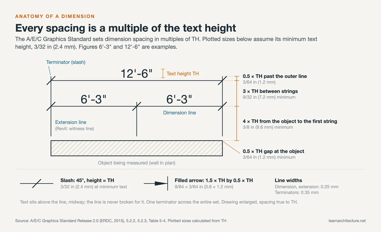
The public A/E/C Graphics Standard published by the US Army Engineer Research and Development Center is one of the few freely available documents that sets these parts out with numbers. It was written to document drafting practice across the US Army Corps of Engineers and other federal agencies, and it draws on the Uniform Drawing System of the US National CAD Standard. Its Release 2.0 (August 2015) places dimension text above the dimension line, preferably midway between the terminators, and says the dimension line is never broken to fit the text, except for angular dimensions.
Terminators can be 45 degree slashes or filled arrowheads. The slash stays legible where many short dimensions meet at one extension line, which makes it a practical choice for plans. Whichever you pick, the same standard requires it to be consistent across the entire set. Line widths come from the line weight hierarchy of the drawing: 0.25 mm for dimension and extension lines and 0.35 mm for terminators in the A/E/C table. ISO 129-1 makes the same point in general terms, requiring dimension lines to be drawn as continuous narrow lines.
Dimension Spacing at 3/32 in (2.4 mm) Text
The A/E/C standard expresses spacing as multiples of the dimension text height (TH), which keeps the proportions right at any plot scale. With the standard’s minimum plotted text height of 3/32 in (2.4 mm), the rules work out as follows.
The multipliers come from the A/E/C Graphics Standard, section 5.2.2; the plotted values are simple multiplication.
| Setting | Rule | Plotted size |
|---|---|---|
| First string from the drawing outline | At least 4 × TH | 3/8 in (9.6 mm) |
| Gap between parallel strings | At least 3 × TH | 9/32 in (7.2 mm) |
| Extension line gap from the object | At least 0.5 × TH | 3/64 in (1.2 mm) |
| Extension line past the dimension line | 0.5 × TH | 3/64 in (1.2 mm) |
| Slash terminator | 45 degrees, height = TH | 3/32 in (2.4 mm) |
| Filled arrowhead | 1.5 × TH wide, 0.5 × TH high | 9/64 × 3/64 in (3.6 × 1.2 mm) |
The small gap between an extension line and the object matters more than it looks. Without it, the extension line reads as part of the wall, and on a busy plan the reader loses track of which line is building and which is annotation.
🔢 Quick Numbers
- 3/32 in (2.4 mm): minimum plotted height for dimension text in the A/E/C Graphics Standard, Release 2.0
- 1/16 in (1.5 mm): the smallest fraction that standard allows on a drawing, because site accuracy rarely needs more
- 2 decimals: the maximum for elevation figures such as EL 241.56 in the same standard
- September 2025: publication of Version 7 of the US National CAD Standard, according to the NCS FAQ
Architectural Dimension Standards Worth Knowing
No single rulebook governs every office, but three documents come up again and again.
In the United States, the reference point is the Uniform Drawing System inside the National CAD Standard, maintained by the National Institute of Building Sciences. Its Drafting Conventions module covers drawing orientation, layout, line types, dimensions, drawing scale and notation. The NCS itself is a paid document, which is why the federal A/E/C standard built on it is so useful for students.
Internationally, ISO 129-1:2018 sets the general principles for presenting dimensions and tolerances on 2D technical drawings in all disciplines and trades. Its scope note points construction users to ISO 6284 for additional building-specific detail. Its value to architects lies mainly in vocabulary: chain, parallel, running and coordinate dimensioning are all defined there.
In the UK, BS 8888 is often mentioned in the same breath, but check its audience before adopting it. BSI describes BS 8888:2025 as the national framework for technical product documentation aimed at mechanical, design and manufacturing engineers in sectors such as aerospace, automotive and medical devices. For building drawings it is useful background on the ISO system rather than a day-to-day rulebook. Whatever the national standard, the office standard and the client’s CAD requirements usually decide the details, so read those first.
Dimension Strings: Chain, Baseline and Running Dimensions
Individual dimensions are grouped into dimension strings, and the way a string is built changes how errors behave.
Chain (Continuous) Dimensions
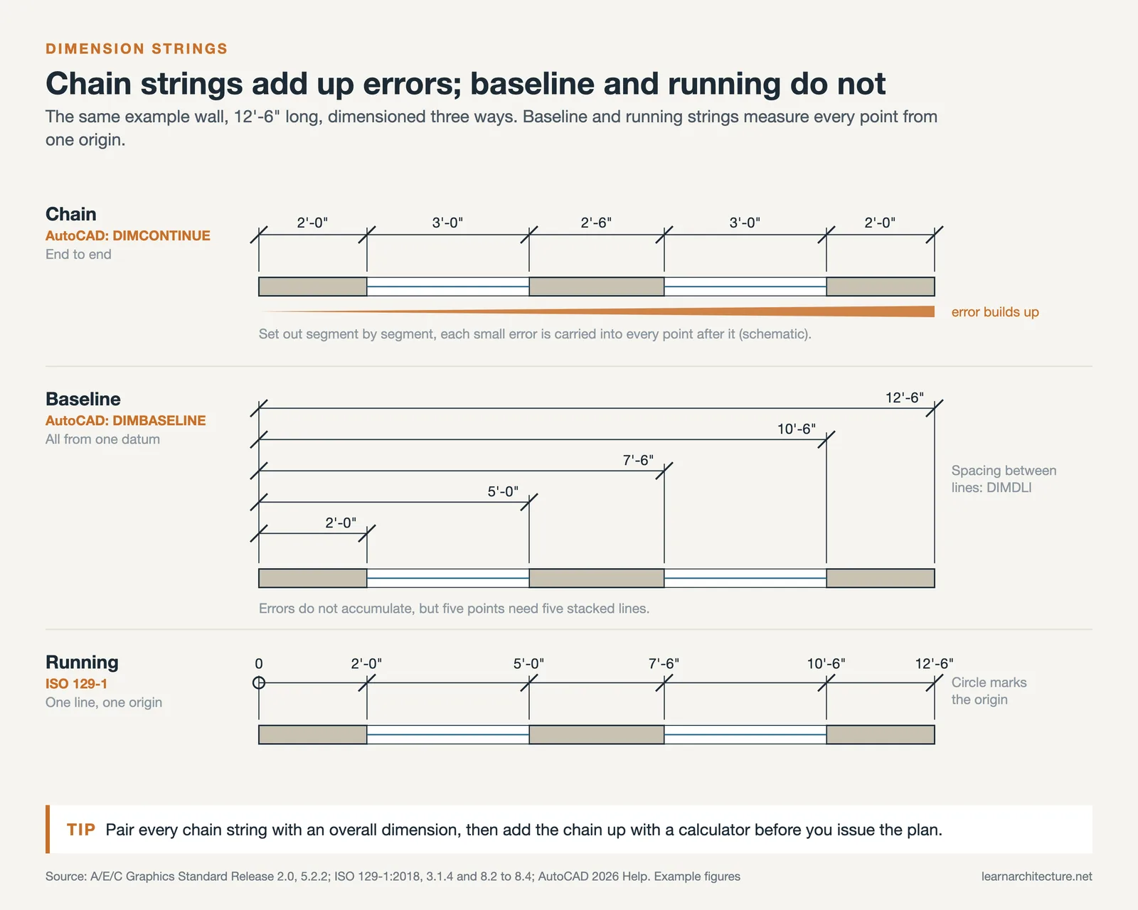
A chain string places dimensions end to end along one line: wall to window, window to window, window to corner. It is the default on architectural plans, and the A/E/C standard states a preference for continuous dimension lines over staggered ones. In AutoCAD the command is DIMCONTINUE, which starts each new dimension from the second extension line of the previous one and lines the dimension lines up automatically.
The weakness of a chain is accumulation. If the contractor sets out each segment from the end of the last one, small errors add up along the wall. That is why a chain string is always paired with an overall dimension that checks it.
Baseline (Parallel) Dimensions
Baseline dimensioning measures every point from one shared datum, stacking the dimension lines in parallel. AutoCAD’s DIMBASELINE does this, with the spacing between lines set by the DIMDLI system variable. Because every figure comes from the same origin, errors do not accumulate. The cost is space: five points need five stacked lines.
Running Dimensions
Running dimensions solve the space problem. They also measure from a single origin, but share one dimension line, with the origin marked by a small circle and each point carrying its cumulative distance. ISO 129-1 defines the origin symbol as the circle that indicates the start of running or coordinate dimensioning. Running dimensions suit long elevations, curtain wall mullion setting out and structural grids, where a site engineer measures everything from one control line anyway.
How to Dimension a Floor Plan, String by String
A floor plan is dimensioned from the outside in and from the general to the particular. The floor plan drawing process produces the geometry; dimensioning then reads it back in layers.
Exterior Strings
Place dimensions outside the drawing wherever possible. The A/E/C standard prefers the top and right-hand side of the plan. A reliable arrangement is three strings along each face:
- The string nearest the building locates openings and wall breaks.
- The middle string locates structural grids, columns or major wall junctions.
- The outer string gives the overall length, which checks the other two.
Arranged this way, the least-changing figure sits furthest out, and the reader can move from overall size to detail in one glance.
Choose One Reference and State It
Before placing a single dimension, decide what you measure to: structural grid, face of stud or blockwork, face of finish, or wall centerline. Different offices choose differently, and the choice matters less than applying it everywhere. Revit makes the choice explicit: when you add an aligned dimension, the options bar offers wall centerlines, wall faces, center of core and faces of core. Record the decision in a general note so the builder does not have to guess from context.
Openings and Interior Dimensions
Openings are located either by their centerline or by their edges. Revit’s automatic wall dimensioning offers the same choice as Centers or Widths. Centerlines suit framed walls where the rough opening is built around a set point; edges suit masonry and concrete, where the opening itself is the thing being formed. Door and window sizes then come from the schedule rather than a dimension on the plan.
Interior strings locate partitions from a structural reference. Rooms that need finer control, such as stairs, lift cores and toilets, go on enlarged plans. The plan they come from should point to the enlargement, not repeat its dimensions.
💡 Pro Tip
Before issuing a plan, add up every chain string with a calculator and compare it to the overall figure beside it. Mismatches usually trace back to a wall that moved after dimensioning or to a text override. Ten minutes of arithmetic here saves a site query later.
Where a clearance matters more than a position, say so. A dimension marked as a clear dimension measures between finished faces and tells the builder which figure to protect if tolerances run out. Revit’s equality constraint, shown as EQ on a multi-segment string, does something similar for design intent: it keeps the referenced elements at equal spacing while it is active.
Units and Notation: Feet-Inches and Millimetres
Notation errors are small on paper and expensive on site, so fix the conventions at the start of the project.
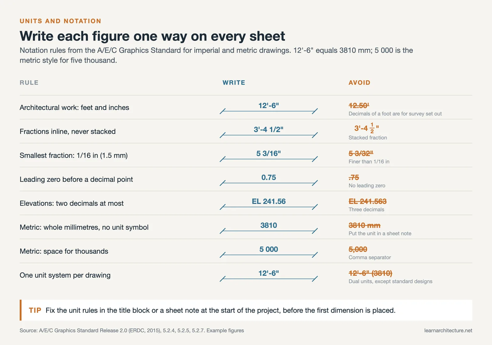
In imperial practice, architectural dimensions are given in feet and inches, written as 12′-6″ (3810 mm). The A/E/C standard keeps fractions inline rather than stacked, sets 1/16 in (1.5 mm) as the smallest fraction, and requires a leading zero before a decimal point for values under one. It reserves decimals of a foot for work set out with survey equipment, such as foundation locations, and limits elevation figures to two decimals.
📐 Technical Note
For metric drawings, the A/E/C Graphics Standard (section 5.2.7) prefers whole millimetres with no unit symbol, backed by a sheet note stating that all dimensions are in millimetres unless otherwise noted. Metres, given to three decimal places, are for site plans and drawings at scales smaller than 1:200. Four-digit and larger numbers use a space, not a comma: 5 000, not 5,000.
The same standard advises against dual units on one drawing, allowing them only for standard designs meant for both systems or for products available only in inch-pound sizes. If your audience is mixed, a units note in the title block and sheet notes is safer than doubling every figure.
Architectural Dimensioning Rules That Keep a Set Consistent
Most dimensioning guidance reduces to a handful of rules. The A/E/C standard states several directly, and the rest follow from the three tests above.
- Dimension each distance once, on one view only. The A/E/C standard forbids shared dimensions between views.
- Place the dimension on the view that shows its true length. A sloping roof is dimensioned in section, not on the plan.
- Keep dimension text the same height as the other text on the drawing.
- Keep the same terminator across the whole set.
- Do not run dimension text across hatching or poché. Move the string or break the hatch pattern behind the figure so the number stays readable.
- Let the schedule and the enlarged plan own their information; the general plan only points to them.
⚠️ Common Mistake to Avoid
Typing a new value over a measured dimension to make the plan “look right”. The A/E/C Graphics Standard strongly discourages edited or exploded dimensions and strictly prohibits exploding one to show a value different from the measured one. If the number is wrong, move the geometry. An overridden figure no longer updates when the design changes, and it silently breaks the arithmetic of the whole string.
A related habit is to lock the associativity. In CAD and BIM, a dimension attached to the wall it measures moves when the wall moves. A dimension drawn from loose lines, or one that lost its link during an export, stays put and becomes wrong without anyone noticing. Checking a sample of dimensions after every major design change is cheaper than finding the drift on site.
Putting It All Together
Dimensioning architectural drawings is the point where drawing conventions stop being about appearance and start carrying liability. Scale, line weight, title blocks and hatching make a sheet readable; the numbers make it buildable.
Quick Recap:
- Pick one reference system, state it in a note, and apply it on every sheet.
- Stack strings from openings to grids to overall, outside the plan, and check that they close.
- Choose chain, baseline or running dimensions deliberately, knowing how each handles error.
- Never override a measured value; fix the model instead.











Leave a comment