

Table of Contents Show
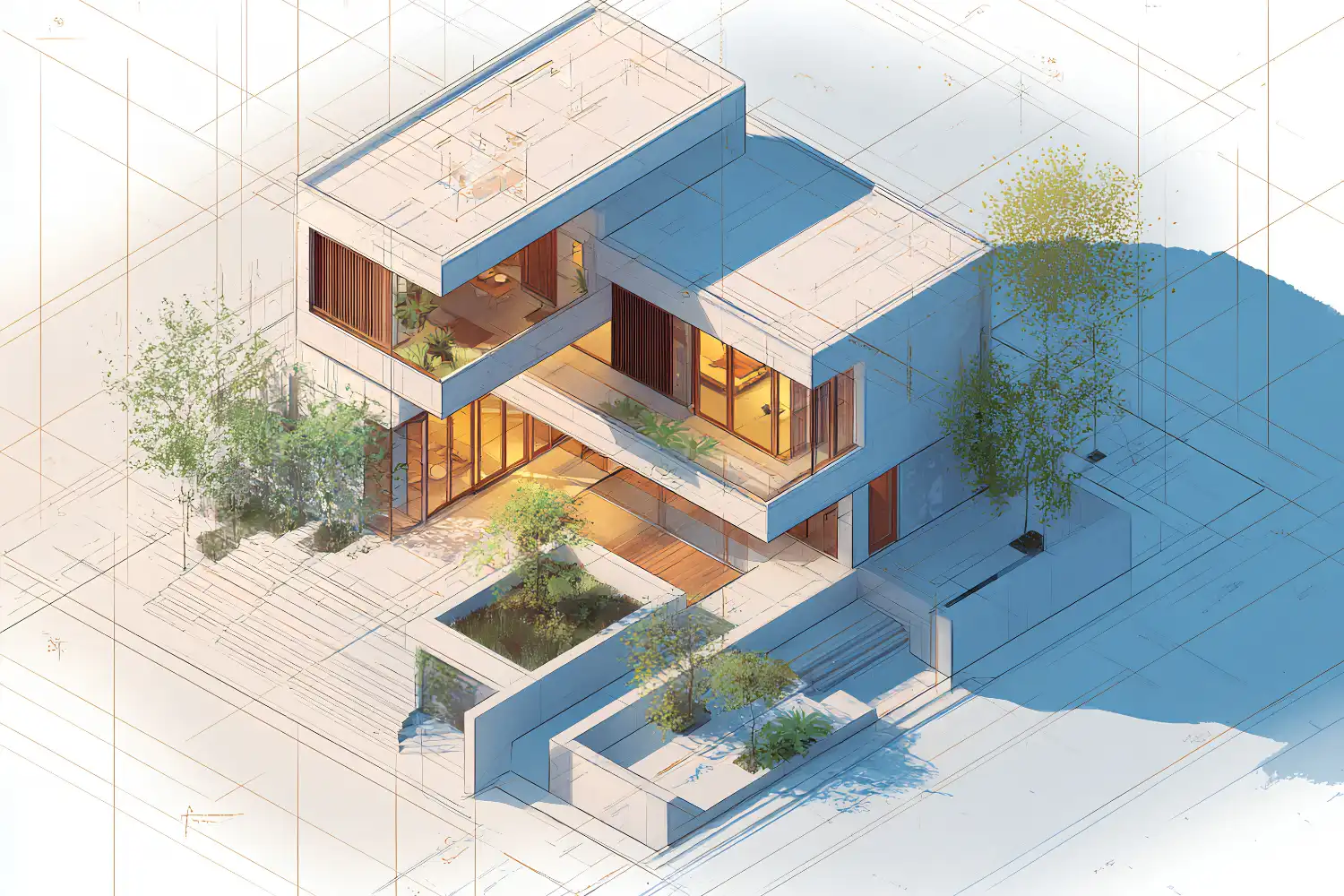
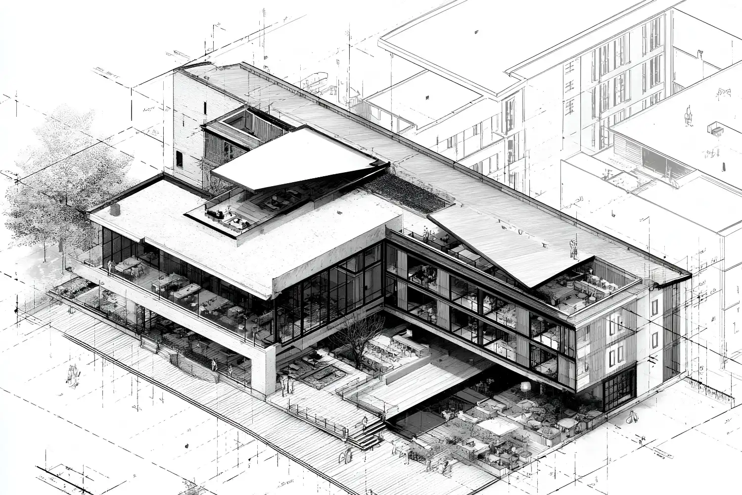
Isometric drawing for architecture is a method of representing three-dimensional buildings and spaces on a flat surface using equal 30-degree angles along all three axes. Unlike perspective drawing, isometric projection keeps dimensions true to scale, making it one of the most practical tools for communicating spatial ideas, construction details, and design concepts in architectural practice and education.
What Is an Isometric Drawing in Architecture?
An isometric architectural drawing translates a 3D structure into a 2D image where the X, Y, and Z axes are equally foreshortened and separated by 120-degree intervals. The word “isometric” comes from Greek, meaning “equal measure.” Because all three axes share the same scale, measurements taken from any direction remain accurate and comparable. This sets isometric drawing apart from perspective views, where objects shrink as they recede from the viewer.
Architects and designers rely on isometric drawings architecture to accomplish several things at once: they can show floor plans, elevations, and roof forms in a single image. They also expose spatial relationships between rooms, levels, and structural elements without the visual distortion that comes with vanishing points. For a broader look at how different types of architectural diagrams communicate design intent, it helps to see where isometrics fit within the wider family of representation tools.
📐 Technical Note
In true isometric projection (per ISO 5456-3), all three axes are inclined at 120 degrees to each other, and the foreshortening factor is approximately 0.816 for each axis. Most architectural isometrics skip this reduction and draw at full scale along all axes, which technically makes them “isometric drawings” rather than “isometric projections.” The visual difference is a slight size increase, but proportions remain identical.
This type of drawing differs from other axonometric projections like dimetric or trimetric views, where two or all three axes have different scales. The equal-scale property of isometric drawing in architecture makes it the preferred choice for most educational and presentation contexts because it is simpler to construct and easier to read.
How to Create an Isometric Architectural Drawing
Building an isometric architectural drawing follows a clear sequence whether you work by hand or digitally. The process starts with the grid, moves to primary volumes, and finishes with detail layers. Below is a step-by-step breakdown.
Setting Up the Grid and Axes
Start with a vertical line for the Z axis (height). From its base, draw two lines at 30 degrees to the horizontal, one going left and one going right. These represent the X and Y axes (width and depth). Every line in your drawing will run parallel to one of these three directions. If you are working on paper, a 30/60-degree set square speeds this up. In software like SketchUp, you can switch from perspective to parallel projection and rotate the camera to a standard isometric angle to get the same result automatically.
Set your scale before you draw anything. If you are working at 1:100, a 3-meter wall height equals 30 mm on paper. Keep the same scale along all three axes. This is one of the fundamental advantages of isometric drawing architecture: you can pull accurate measurements directly off the drawing without conversion tables. For students learning the basics of architectural symbols and conventions, isometrics are a good first exercise because the geometry is consistent and predictable.
💡 Pro Tip
When setting up an isometric grid by hand, lightly draw your 30-degree guidelines across the entire sheet before committing to any building geometry. Erasing stray construction lines later is much faster than correcting angles mid-drawing, and a full grid helps you spot alignment errors between separated building components early.
Building Volume and Detail
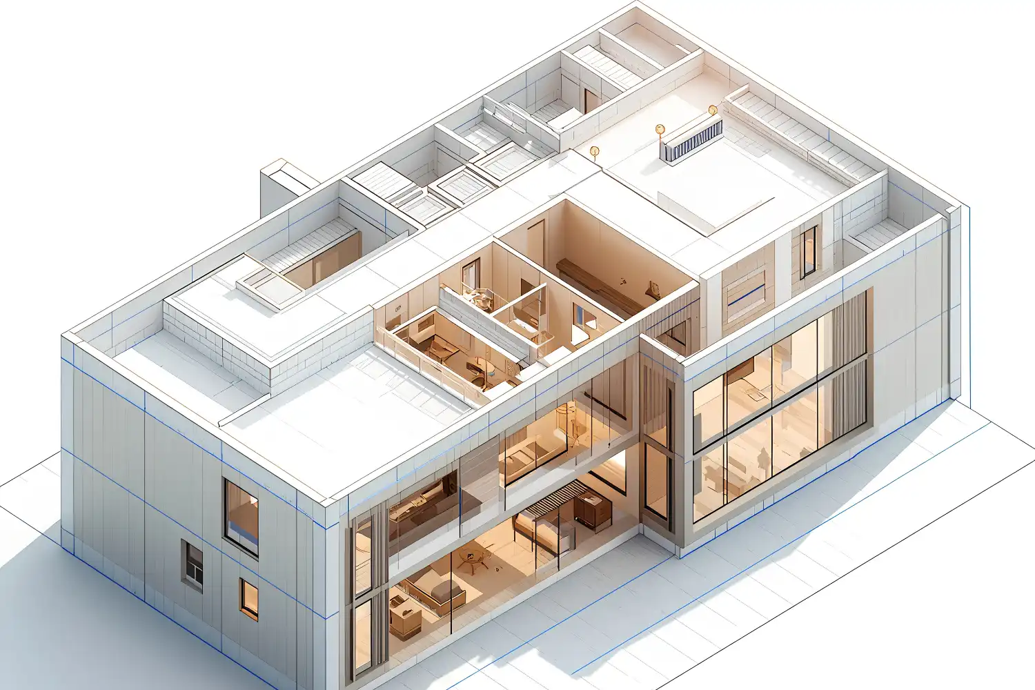
With the grid established, begin with the building footprint. Draw the plan outline along the X and Y axes, then extrude vertical edges upward along the Z axis to the correct wall height. Connect the tops to form the roof plane. At this stage, your drawing should look like a transparent wireframe box shaped to match the building massing.
Next, add openings. Windows and doors are rectangular cutouts positioned along the wall planes. Because isometric drawings use parallel lines instead of converging ones, every window on the same wall face will appear the same width, regardless of how far it is from the viewer. This clarity makes isometric drawings architecture a strong tool for checking facade proportions and repeating module rhythms.
Finish by layering in context and materiality. Hatching, line weight variation, shade, and shadow all help distinguish between walls, glazing, ground planes, and vegetation. Circles in isometric views become ellipses, so door arcs and circular columns require an ellipse template or the correct CAD tool. For more on choosing the right digital sketching tools for this type of drawing, it is worth comparing the options available for line-based work.
⚠️ Common Mistake to Avoid
A frequent error in isometric architectural drawing is drawing circles as circles rather than ellipses. In an isometric view, any circle lying on one of the three primary planes appears as an ellipse with its major axis perpendicular to the corresponding isometric axis. Using full circles for columns, arched windows, or rounded walls breaks the 3D illusion and signals to reviewers that the drawing fundamentals need more practice.
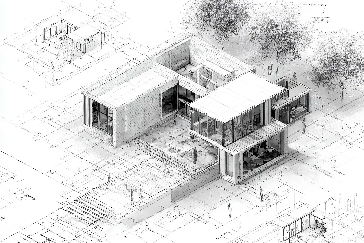
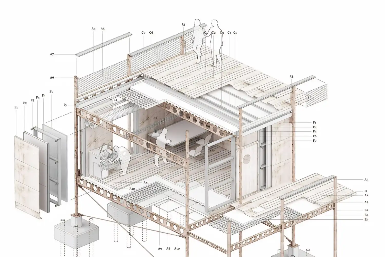
Exploded Isometric Drawings in Architecture
An exploded isometric drawing architecture technique separates a building into its component layers (foundation, structural frame, wall assembly, roof, interior fit-out) and spaces them apart vertically along the Z axis. Each layer stays in its correct X-Y position, so the viewer can read how the parts stack together while seeing every component individually.
This format is especially useful for construction documentation, where trades need to understand how their work interfaces with others. It also appears frequently in student portfolios and competition boards because it communicates design logic, material strategy, and spatial sequence in a single image. If you are developing concept diagrams for a project, an exploded isometric is one of the most effective ways to show how programmatic layers relate to each other.
To create an exploded view, start by modeling or drawing the complete isometric. Duplicate the layers you want to separate, then offset each copy upward by a consistent spacing distance. Add light dashed lines or thin connector lines between corresponding points on adjacent layers so the viewer can track how parts align. Keep the number of separated layers between three and six to avoid visual clutter.
Video: Creating Isometric Architectural Diagrams with SketchUp and Photoshop
This step-by-step tutorial by Learn Upstairs walks through the process of building an isometric architectural diagram from a SketchUp model, rendering it in V-Ray, and refining the final output in Photoshop.
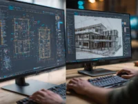
Best Software for Isometric Architecture Drawing
Several tools support architectural isometric drawing at different levels of complexity. The right choice depends on your project stage, output quality needs, and how much control you want over line weight and material representation.
Software Comparison for Isometric Drawings
The table below summarizes the main options available for creating isometric drawings in architecture.
| Software | Best For | Isometric Setup | Learning Curve |
|---|---|---|---|
| SketchUp | Quick massing and diagrammatic views | Camera > Parallel Projection + preset angle | Low |
| Rhino | Complex geometry and NURBS-based forms | Set view to isometric via named views | Medium |
| Revit | BIM-integrated documentation | 3D view with orthographic camera | High |
| Adobe Illustrator | 2D vector diagrams and presentation graphics | Manual grid at 30 degrees or SSR transform | Medium |
| AutoCAD | Technical isometric drafting | ISODRAFT mode with isometric snap | Medium |
SketchUp remains the fastest route for students producing isometric drawings architecture for portfolio boards. Its parallel projection mode converts any 3D model into a clean isometric view that can be exported as a 2D image. For more detailed NURBS-based workflows, Rhino and Grasshopper offer precise control over curves and surface geometry that SketchUp cannot match. Revit is best suited to teams working within BIM environments where the isometric is generated from an existing building model rather than drawn from scratch. A broader comparison of modeling tools is available in this overview of 3D architectural design software.
💡 Pro Tip
If you use SketchUp for your isometric architecture drawing, export your view as a PDF or SVG rather than a raster image. This preserves vector line quality and allows you to refine line weights, add hatching, and overlay color in Illustrator or Photoshop without pixelation. Many architecture studios follow this exact two-step workflow for competition and publication boards.
Post-processing plays a large role in the final quality of any architectural isometric drawing. Software like Adobe Photoshop and Illustrator are commonly paired with 3D tools to adjust shadows, add entourage (people, trees, furniture), and control the graphic hierarchy of the drawing. For more on combining 3D modeling with post-production rendering, see this breakdown of architectural visualization tools and workflow.
Where to Go From Here
Your Next Step: Open your current project in SketchUp or Rhino, switch to parallel projection, and set the camera to a standard isometric angle. Export the raw line drawing and spend 30 minutes in Illustrator or Photoshop adjusting line weights and adding a simple shadow layer. This single exercise will teach you more about isometric drawing for architecture than any amount of reading alone.
Frequently Asked Questions
What is the difference between isometric and perspective drawing in architecture?
Perspective drawing uses vanishing points that cause parallel lines to converge, mimicking how the human eye perceives depth. Isometric drawing keeps all parallel lines truly parallel and maintains equal scale on all three axes. This makes isometric views better for accurate measurement and technical communication, while perspective views are better for realistic visual impressions. For a related look at vertical slicing techniques, section drawings offer another approach to revealing interior spatial relationships.
Which software is easiest for beginners to create isometric architecture drawings?
SketchUp is widely considered the most accessible starting point. Its push-pull modeling approach and one-click parallel projection toggle let beginners produce a clean isometric view within minutes of creating a basic 3D model. No manual grid construction is needed because the software handles the axonometric camera setup internally.
How do you draw circles and curves in an isometric view?
Circles on any of the three isometric planes appear as ellipses. For hand drawing, use an ellipse template aligned to the correct isometric plane. In CAD software like AutoCAD, the ISODRAFT mode includes an isometric ellipse (Isocircle) tool that draws the correct ellipse automatically based on which isoplane you have selected.
What are exploded isometric drawings used for in architecture?
Exploded isometric drawings separate a building into its constituent layers (structure, envelope, interior, services) and space them apart along the vertical axis. They are used in construction documentation to show assembly sequences, in student portfolios to communicate design logic, and in competition presentations to reveal how programmatic or material systems interact across the building.
- architectural isometric drawing
- architectural isometric drawing software
- architecture isometric drawing
- exploded isometric drawing architecture
- isometric architectural drawing
- Isometric architecture drawing
- isometric drawing architecture
- isometric drawing architecture tutorial
- isometric drawing in architecture
- isometric drawings architecture


Leave a comment