


Table of Contents Show
Quick Answer
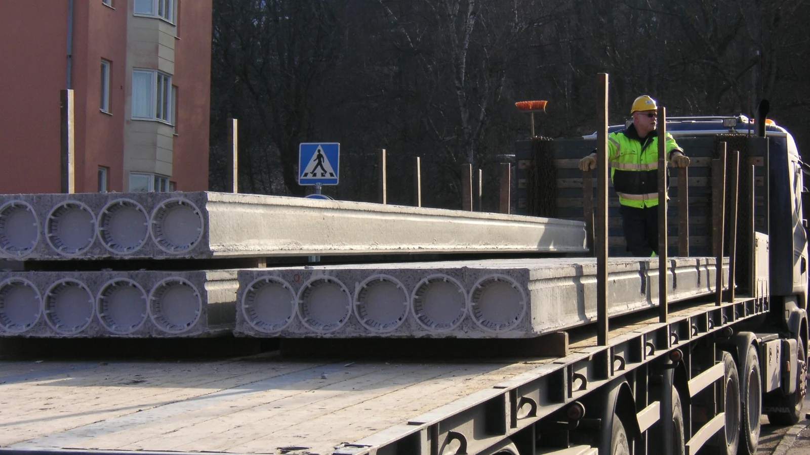
A hollow core slab is a precast, prestressed concrete floor plank with continuous voids running its full length. Units are normally 1200 mm wide in Europe and 48 inches wide in North America, with depths from about 150 to 500 mm, and residential spans range from roughly 7.5 m to 18 m.

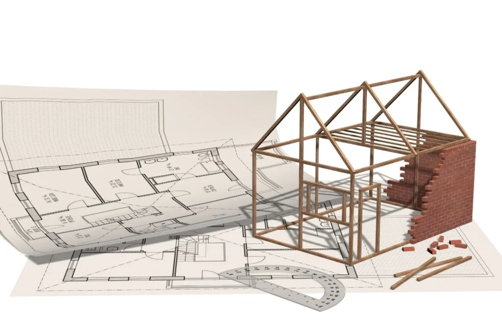


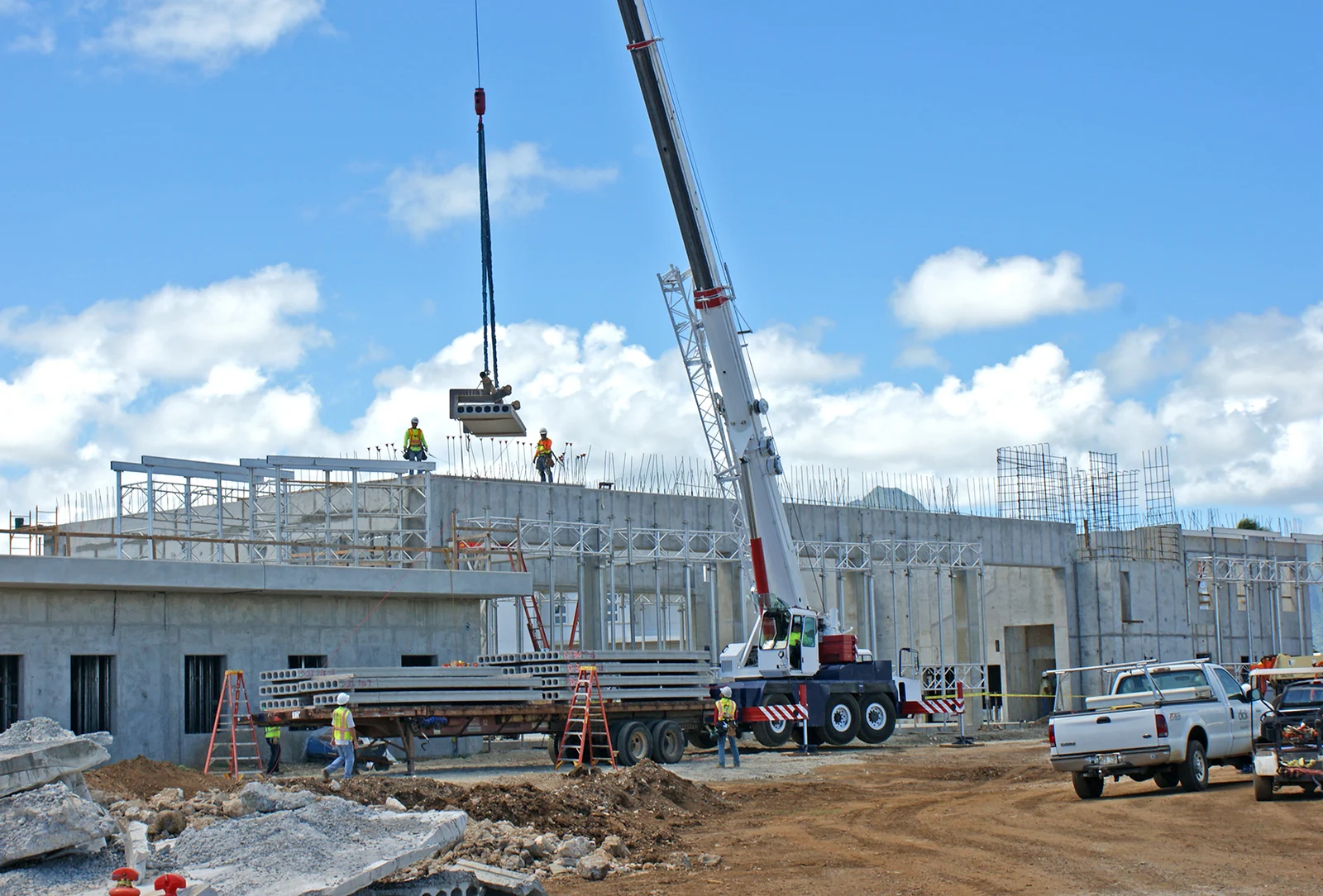
Few floor systems arrive on site as finished as a hollow core slab. The plank is cut to length in the factory, lifted off a truck by crane, set on its bearings and grouted, and the next trade can walk on it the same day. That speed is why manufacturers list multi-occupancy housing, offices, schools, car parks and retail among its typical uses.
For a designer, the useful questions are more specific than “is it fast?” Which depth do I need for this span? How wide is a unit, and should my grid follow it? How much does a topping add, and where can I cut holes for services? The figures below come from published manufacturer and trade association tables, so you can check every number against its source.
What Is a Hollow Core Slab?
The European product standard EN 1168 defines the element precisely: a monolithic prestressed or reinforced unit of constant depth, split into an upper and a lower flange joined by vertical webs, with longitudinal voids of constant cross-section. The International Prestressed Hollowcore Association summarises that definition in its history of hollow core slab development, written by Arnold Van Acker and Stef Maas.
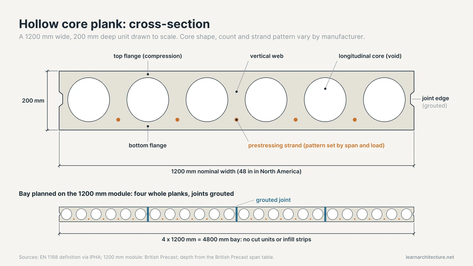
The logic is structural efficiency. In a solid slab spanning between supports, the concrete near mid-depth does little work in bending. Removing it as round or elongated cores cuts self-weight while keeping the top and bottom flanges, which carry compression and house the prestressing strand. Less dead load means the plank can spend more of its capacity on the loads you actually care about: people, partitions, furniture and finishes.
Prestressing is the second half of the idea. High-strength strands are tensioned along long steel casting beds before the concrete is placed. Once the concrete hardens, the strands are released and the plank is saw-cut to length. The stored compression lets a fairly shallow section span much further than an ordinary reinforced slab of the same depth, and it also gives every unit a slight upward camber, which matters later for finishes.
How Hollow Core Planks Are Made
Three production methods exist. Wet casting uses void formers placed in a mould. Slipforming drags a moving mould along the bed while concrete is compacted inside it. Extrusion forces a very dry, low-slump mix through a machine that forms the cores as it travels. The technical manual of the National Precast Concrete Association Australia (NPCAA) puts typical steel casting beds at 120 m to 170 m long, heated from underneath to shorten curing, with each plank saw-cut on the bed to the length on the drawings.
Oldcastle Infrastructure, for instance, extrudes the planks described in its Elematic hollow-core plank technical guide on 500 ft steel beds, with prestressing strands placed at the spacing the span, load and fire cover require. Because the strand pattern changes with the design, two planks of identical depth can carry very different loads.
📌 Did You Know?
The idea is older than prestressing. Van Acker and Maas trace longitudinal void formers in concrete slabs to a German patent by Wilhelm Siegler in 1906, and note that the American company Spancrete bought Wilhelm Schäfer’s slipform patent and began producing prestressed hollow core elements around 1950.
Standard Hollow Core Slab Sizes
Widths are the easiest dimension to pin down because almost every plant works to one module. Depths vary more, since each manufacturer runs its own set of extruder or slipform profiles.
Widths: the 1200 mm and 4 ft Module
British Precast, the UK trade body, states in its Hollowcore Floor Systems guidance that slabs are generally manufactured 1200 mm wide and can be cut narrower for particular layouts. In the United States the equivalent module is 48 inches, which is the standard width Oldcastle quotes for its planks. Australia follows the metric module: NPCAA advises in its Hollowcore Flooring Technical Manual that floor plan dimensions should preferably suit a 1200 mm module, with longitudinally cut planks, wet-cast panels or an in-situ strip used to make up odd widths.
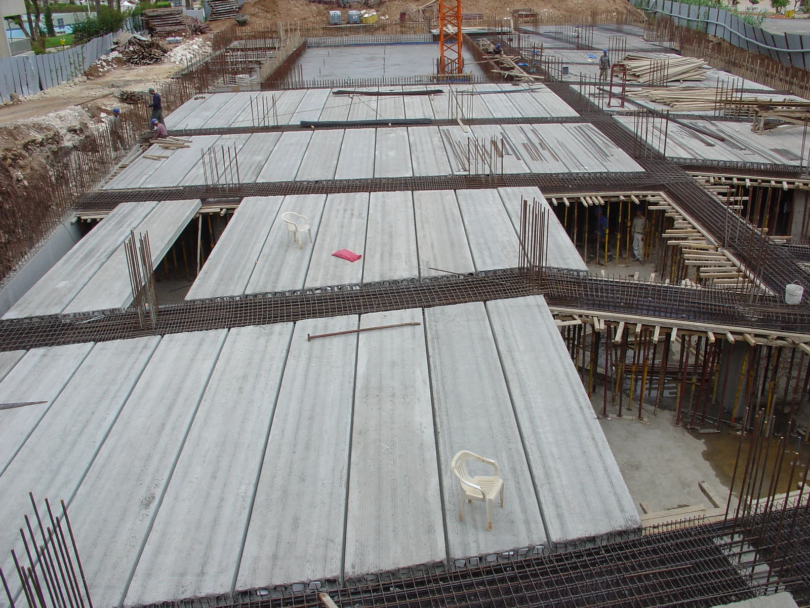
That module has a direct consequence for planning. If your bay widths and wall positions sit on multiples of 1200 mm (or 4 ft), the floor goes down as whole planks. Every non-modular dimension adds a cut unit or a cast-in strip, both of which cost time on site. A structural grid set out with the plank width in mind is the cheapest design decision you can make with this system.
Depths
British Precast gives a typical depth range of 100 mm to 500 mm. FP McCann, one of the larger UK producers, publishes units from 150 mm to 500 mm deep in its flooring brochure, plus a separate 100 mm floor slab. Oldcastle’s North American range is narrower and coarser: 8, 10, 12 and 16 inches thick, roughly 203, 254, 305 and 406 mm.
Self-weight rises with depth, though not in proportion, because deeper sections carry proportionally larger voids. In the FP McCann table a 150 mm unit weighs 2.36 kN/m², a 300 mm unit 3.99 kN/m² and a 500 mm unit 5.92 kN/m². Doubling the depth from 150 to 300 mm adds about 69 percent to the weight, while the clear span at light domestic load roughly doubles.
Hollow Core Slab Span Tables
Span is where hollow core earns its place, and also where most early-stage mistakes happen. Published tables are guides for preliminary sizing only. The manufacturer’s engineer designs the strand pattern for the actual loads, openings and fire rating.
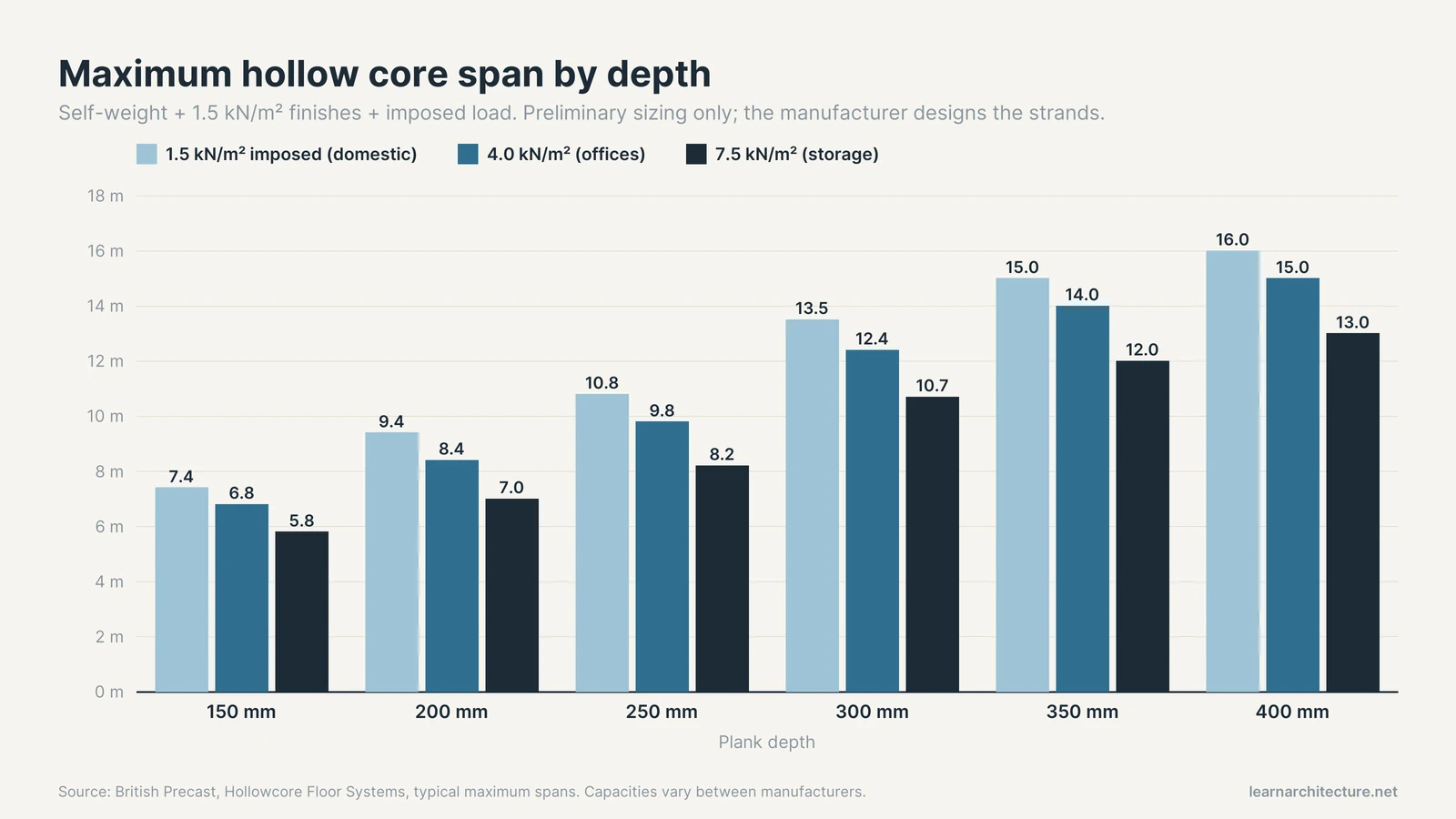
Typical Maximum Spans by Depth (British Precast)
The British Precast table below assumes the unit’s self-weight plus 1.5 kN/m² for finishes, with the imposed load in each row on top. Roughly, 1.5 kN/m² corresponds to domestic floors, 2.5 to 4.0 kN/m² to offices and 5.0 to 7.5 kN/m² to storage.
| Imposed load (kN/m²) | 150 mm | 200 mm | 250 mm | 300 mm | 350 mm | 400 mm |
|---|---|---|---|---|---|---|
| 1.5 | 7.4 m | 9.4 m | 10.8 m | 13.5 m | 15.0 m | 16.0 m |
| 2.5 | 7.4 m | 9.2 m | 10.8 m | 13.5 m | 14.7 m | 16.0 m |
| 4.0 | 6.8 m | 8.4 m | 9.8 m | 12.4 m | 14.0 m | 15.0 m |
| 5.0 | 6.4 m | 7.9 m | 9.3 m | 11.8 m | 13.2 m | 14.3 m |
| 7.5 | 5.8 m | 7.0 m | 8.2 m | 10.7 m | 12.0 m | 13.0 m |
British Precast adds that load and span capacity vary between manufacturers, and that exposure, openings, camber, deflection and vibration all need checking. Treat the figures as a starting depth, not a final answer.
Manufacturer Example: FP McCann Units From 150 to 500 mm
Individual producers often publish slightly different numbers because their core profiles and strand patterns differ. FP McCann’s table uses the same basis (live load plus self-weight plus 1.5 kN/m² finishes) and extends to deeper units:
| Unit depth | Self-weight (kN/m²) | Span at 1.5 kN/m² | Span at 5.0 kN/m² | Span at 10 kN/m² |
|---|---|---|---|---|
| 150 mm | 2.36 | 7.50 m | 6.60 m | 5.20 m |
| 200 mm | 2.98 | 9.90 m | 7.90 m | 6.30 m |
| 250 mm | 3.62 | 11.70 m | 9.30 m | 7.50 m |
| 300 mm | 3.99 | 14.30 m | 11.90 m | 9.70 m |
| 400 mm | 4.77 | 17.00 m | 14.40 m | 12.10 m |
| 500 mm | 5.92 | 18.00 m | 16.50 m | 13.90 m |
Two patterns stand out. First, the 150 mm unit tops out at 7.50 m under light loads in this table, so a small domestic plan rarely needs anything deeper. Second, past about 400 mm the gains flatten: the extra 100 mm to reach 500 mm buys only 1 m of span at domestic load. Long spans at that end of the range often push designers toward a composite topping or a different system.
Span-to-Depth Ratios for Quick Sizing
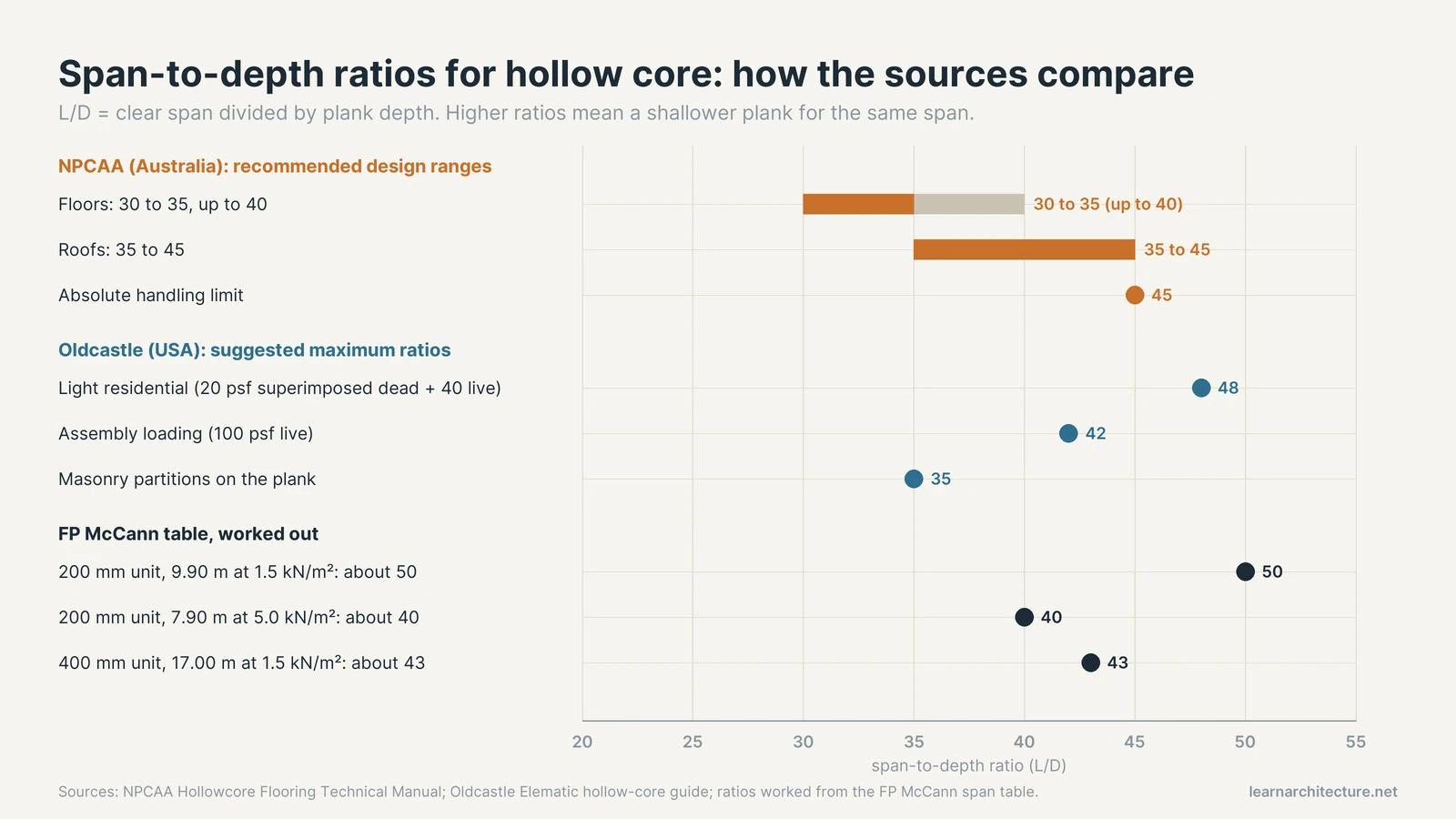
When you only need a first guess, a span-to-depth ratio is faster than a table. The sources disagree more than you might expect, and the reason is instructive. The NPCAA manual recommends keeping floors in the range of 30 to 35, up to 40, to control deflection and vibration, with roofs at 35 to 45 and an absolute handling limit of 45. Oldcastle’s US guide is more generous for light residential loading (20 psf superimposed dead load plus 40 psf live load) at 48, drops to 42 for assembly loading of 100 psf live load, and falls to 35 where masonry partitions sit on the plank.
📐 Technical Note
You can check those ratios against the FP McCann table yourself. A 200 mm unit spanning 9.90 m works out to L/D of about 50 at light load, but only about 40 at 5.0 kN/m². A 400 mm unit at 17.00 m is about 43. The ratio is not a property of the plank; it shifts with load, which is why NPCAA’s conservative 30 to 35 band leaves room for vibration and heavy partitions.
Topping, Camber and Bearings
The plank itself is only part of the floor build-up. What goes on top, and what it sits on, decides the final structural depth and how the floor behaves.
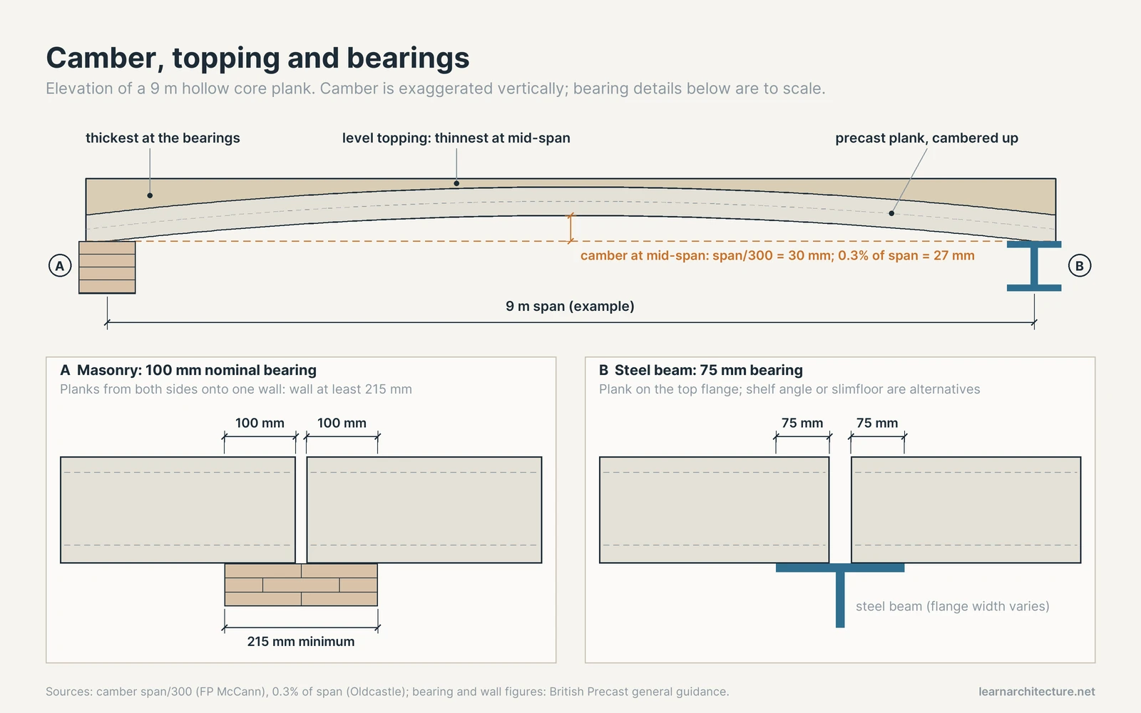
Structural and Non-Structural Toppings
Hollow core can be used with grouted joints only, receiving a screed or another floor finish. A bonded structural topping turns the planks into a composite floor, which helps with heavy point loads, diaphragm action, large penetrations and levelling. NPCAA cites a minimum average structural topping of 50 mm under the Australian standard AS 3600, and notes that 60 mm is commonly used on planks up to 200 mm deep and 80 mm on planks of 300 mm and above. Non-structural self-levelling toppings typically average 10 to 15 mm.
In North America, Oldcastle bases its topped load tables on a 2 in composite topping and gives the plank top surface a raked finish so the topping bonds. If insulation or a vapour barrier separates the topping from the plank, it is non-composite and simply counts as superimposed dead load.
Camber
Every prestressed plank bows upward. FP McCann quotes an inherent pre-camber of generally span/300, and Oldcastle suggests approximating camber as 0.3 percent of the span. On a 9 m span that is roughly 27 to 30 mm at mid-span, which is enough to show in a thin finish or at a door threshold. Because camber peaks at mid-span, a topping laid to a level surface will be thinnest there and thickest at the bearings.
💡 Pro Tip
When adjacent planks have different spans or loads, they will have different cambers. Detail the topping thickness from the highest mid-span point, state on the drawings whether the topping follows the camber or finishes level, and check finished floor levels at stairs and lift doors before the structural depth is frozen.
Bearings and Supports
British Precast gives general guidance of 100 mm nominal bearing on masonry, 75 mm on steel and 75 mm on in-situ or precast concrete of at least C30 grade. Where planks bear from both sides onto one wall, it recommends a wall thickness of at least 215 mm, and never less than 140 mm even with a tie. Planks can sit on steel beams in three common ways: on top of the beam, on a shelf angle, or on the bottom flange in slimfloor construction, which gives an almost flush soffit and the shallowest overall depth. If you are working out which walls carry these loads in an existing building, our guide to identifying a load bearing wall covers the basics.
Openings, Services and Fire Resistance
Holes are the most common reason a hollow core layout changes late in design. The cores and strands that make the plank efficient also limit where you can cut.
Openings and Penetrations
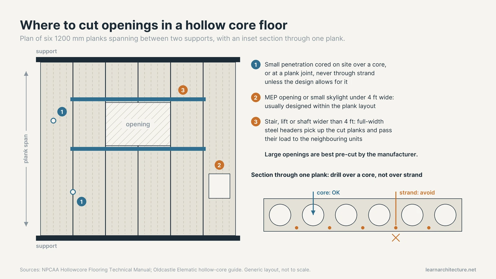
Large openings are best pre-cut by the manufacturer, while small penetrations can be cored on site. NPCAA warns that penetrations should not cut through strands unless the design allows for it, and that large openings may need full-width steel headers that pick up the end of a cut plank and transfer its load to neighbouring units. Oldcastle’s rule of thumb is that MEP openings and small skylights under 4 ft wide can usually be designed within the plank layout, while elevator, stair and shaft openings wider than that need extra structural support. It also suggests adding about 15 psf to the uniform load in residential buildings to account for MEP openings.
⚠️ Common Mistake to Avoid
Sizing planks from a load/span table and then adding service holes later. FP McCann’s table states plainly that it does not allow for reduced capacity from service holes. Mark every riser, soil stack and shaft on the general arrangement before the plank order is placed, and position them over cores or plank joints rather than over strand.
The cores have a secondary use: NPCAA notes they can serve as ducts for plumbing and electrical cables, so long as the routes are agreed with the manufacturer.
Fire and Acoustics
British Precast states that all hollow core slabs have 1 hour fire resistance, which can be enhanced to 2 hours. In FP McCann’s table, units of 300 mm and deeper carry a 2 hour rating as standard. Higher fire ratings usually mean more concrete cover to the strand, and NPCAA cautions that this can push up the overall depth. Concrete mass helps with airborne sound. Oldcastle notes, though, that impact sound ratings depend mostly on the finish laid on the plank, so impact performance between flats comes from the floor build-up rather than the plank alone.
Hollow Core Slab Pros and Cons
The system suits some building types far better than others. Weigh these points against your grid, your services strategy and your programme.
| Aspect | Advantage | Limitation |
|---|---|---|
| Speed | No formwork; immediate working platform once grouted | Needs crane access and a delivery sequence |
| Span | 7.5 m to 18 m at light loads, fewer columns | Spans one way only between supports |
| Weight | Voids cut dead load against a solid slab | Still heavier than timber or steel deck systems |
| Layout | Fast and repetitive on a 1200 mm module | Irregular plans need cut units and infill strips |
| Services | Cores can carry cables; holes pre-formed | Late openings are costly and may need headers |
| Finishes | Soffit can be left exposed in car parks | Camber must be absorbed by topping or screed |
Hollow core is often weighed against in-situ concrete and steel-framed floors. For a broader view of those trade-offs, see our comparison of concrete and steel framing, and our overview of precast concrete types and uses, which places hollow core planks alongside wall panels and other factory-made elements.
See also: researchers testing a timber-concrete floor slab system in Stuttgart, a lighter alternative to all-concrete floors.
What This Means for Your Next Project
Start every hollow core scheme with the module and the span direction. Set the grid so planks run the short way between supports, keep bay widths on multiples of 1200 mm where you can, and pick a provisional depth from the British Precast table using the correct imposed load for the building use. Then add the topping you need, allow for camber in the floor build-up, and draw every shaft and riser before talking to a manufacturer.
Your Next Step: Take one typical bay from your current scheme, read its span against the 2.5 or 5.0 kN/m² row in the table above, and send that bay with its openings marked to two manufacturers for a preliminary strand design. Their answers will tell you quickly whether your assumed floor depth holds.
Span and load figures here are taken from published manufacturer and association guidance for preliminary sizing. Technical specifications should be verified by a licensed structural engineer for your specific project.

















Leave a comment