


Table of Contents Show
Quick Answer
A tensile structure carries load purely through tension in a membrane, cable net or both, held in a curved shape by masts, arches, edge cables or air pressure. The main families are saddle (hypar), cone, arch-supported, ridge and valley, and pneumatic forms, usually built in PTFE-coated glass fibre, PVC-coated polyester or ETFE foil.

A brick wall resists load by being heavy. A tensile roof does the opposite: it carries snow, wind and its own weight by pulling, never by pushing, so the material can be as thin as a millimetre and the whole roof can weigh a few kilograms per square metre. That inversion explains both the drama of these buildings and the discipline they demand from designers.
This guide explains how a tensile structure works, the main geometric types, the three membrane materials you will meet in specifications, how the shape is found, and what three landmark roofs in Munich, Denver and London reveal about the system’s strengths and its costs.
How a Tensile Structure Works
Bernd Stimpfle of the German engineering firm formTL sets out the principle clearly in his chapter on membrane structures for the Springer volume Lightweight Landscape (2016). A membrane carries load as tension in its own plane. Because it has almost no bending stiffness, every new load forces the surface to change shape slightly until it reaches a new equilibrium.
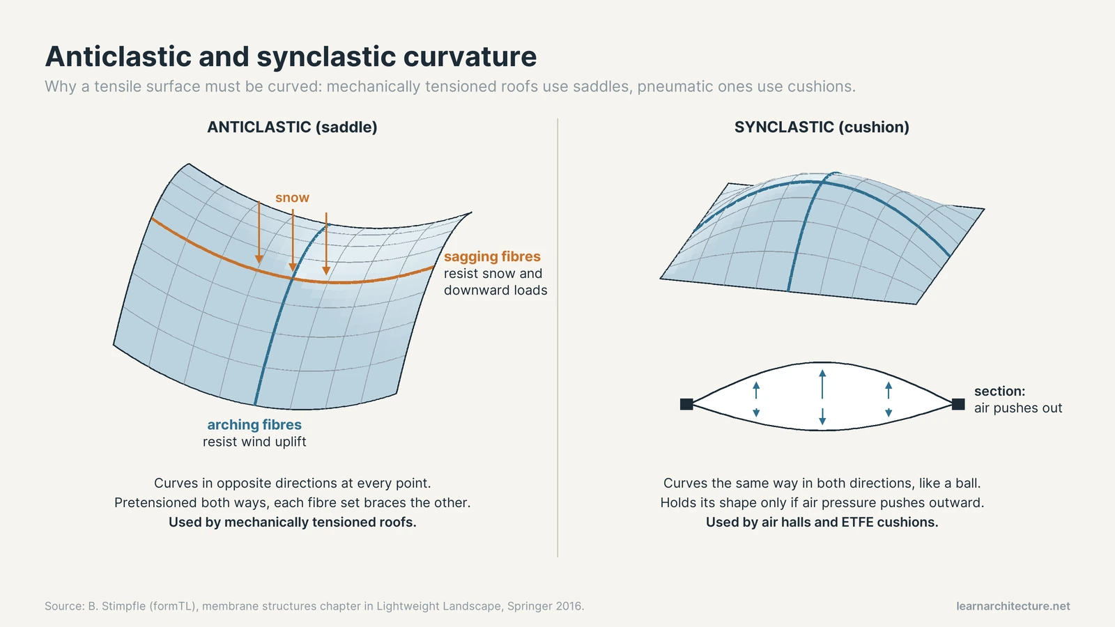
Two conditions make that workable. First, the membrane is pretensioned in both directions, so that it never goes slack and flaps in the wind. Second, the surface is curved. Stimpfle notes that mechanically tensioned structures rely on anticlastic curvature, while pneumatic structures, held up by air pressure, rely on synclastic curvature.
Anticlastic and Synclastic Curvature
Anticlastic means the surface curves in opposite directions at every point, like a horse saddle. Along one axis the fabric sags; along the other it arches. Pull on both sets of fibres and each direction braces the other: downward loads such as snow are resisted by the sagging fibres, while wind uplift is resisted by the arching ones. A flat membrane cannot do this, which is why a perfectly flat stretched sheet is never a real tensile roof.
Synclastic surfaces curve the same way in both directions, like a ball or a cushion. A membrane can only hold that shape if something inside pushes outward, which is the job of air pressure in inflated halls and ETFE cushions.
The stresses do not stay in the fabric. Stimpfle points out that membrane forces concentrate in border, ridge and valley cables, are gathered at nodes and then anchored to the ground or to neighbouring buildings. He also flags the price: structures can start at about 2 kg/m² above the foundation, but the high tension forces demand more foundation work than a conventional roof of the same area.
Types of Tensile Structure
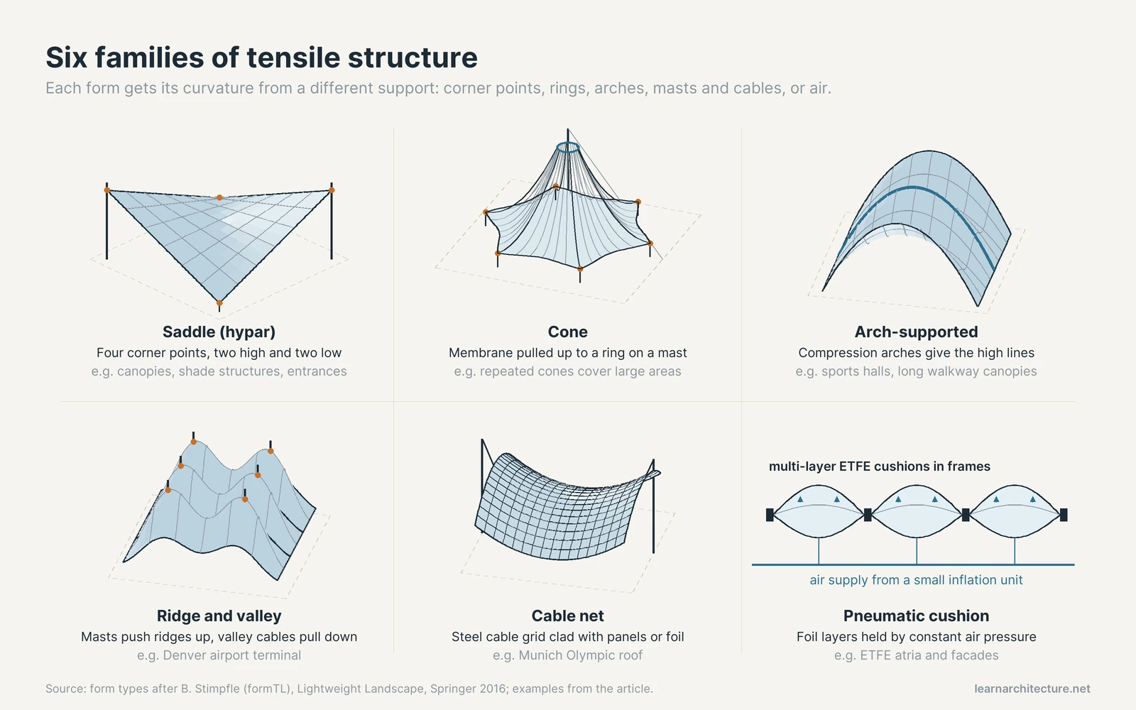
Stimpfle lists the forms that most tensile structures can be grouped into, alone or in combination. Each one gets its curvature from a different kind of support.
Saddle or Hyperbolic Paraboloid (Hypar)
The simplest form uses four corner points, two high and two low, with the edges either fixed or formed by cables. The result is a pure saddle. Hypar sails are common for canopies, shade structures and entrance covers because they need only a few masts and anchors.
Cone
A cone pulls the membrane up to a ring at the top of a mast, or hangs it from a ring on a cable. The tight curvature near the ring makes cones stiff, and repeated cones can cover large areas in a modular way.
Arch-Supported Membranes
Here, compression arches give the membrane its high lines, with the fabric tensioned between them. The arches take compression; the fabric takes tension. Many sports hall covers and long walkway canopies use this logic.
Ridge and Valley
Alternating ridge cables (pushed up by masts) and valley cables (pulled down) fold the membrane into a series of peaks. Stimpfle compares the type to folded plates. Denver’s airport terminal, covered below, is one of the largest examples.
Cable Nets and Pneumatic Forms
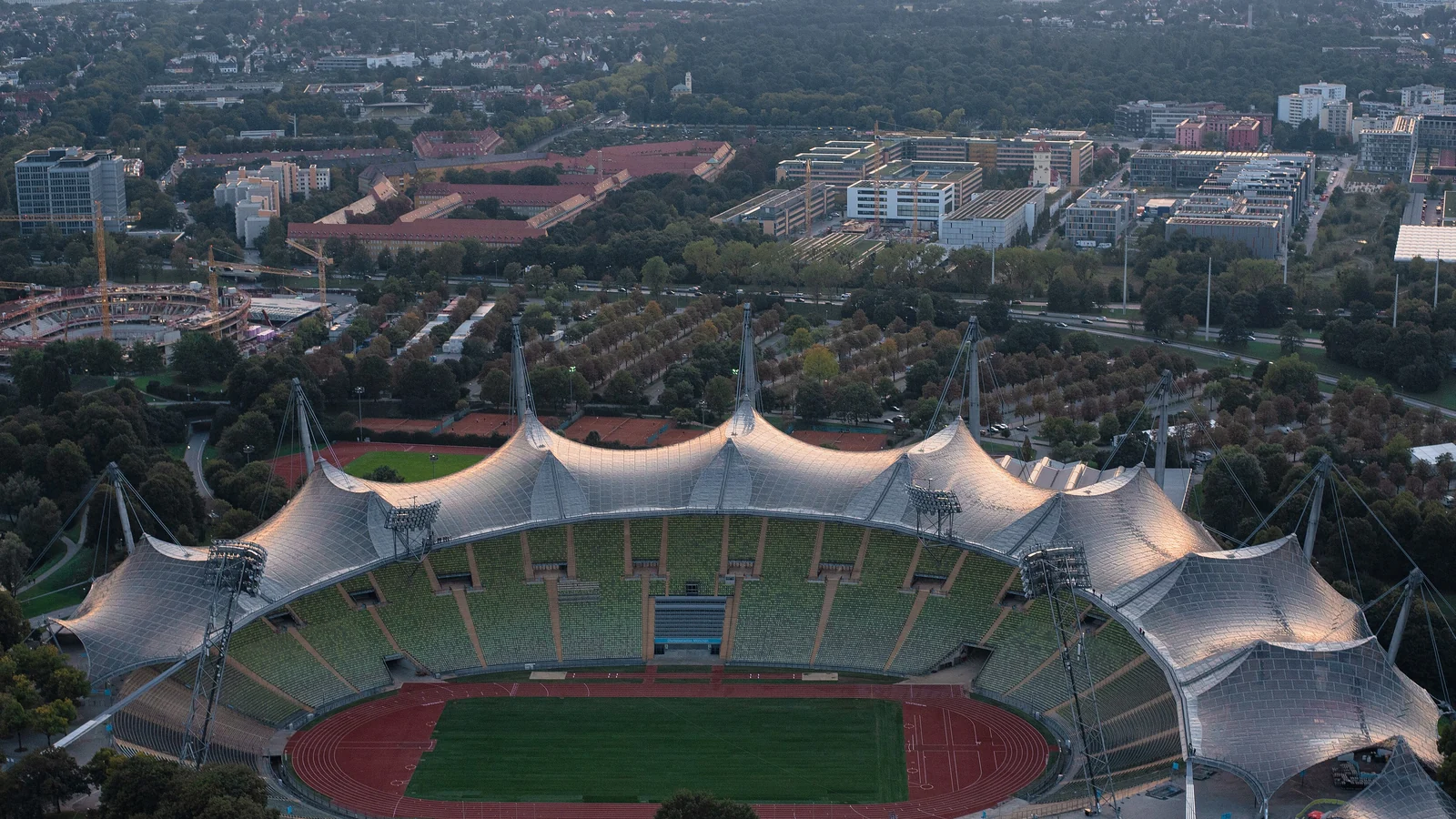
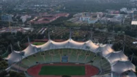
A cable net replaces the fabric with a grid of steel cables, which can then be clad with rigid panels or foil. Munich’s Olympic roof is the classic case. Pneumatic structures complete the family: air-supported halls, single bubbles, and cushions of two or more foil layers kept under constant air pressure.
Tensile Structure Materials: PTFE, PVC and ETFE
Three materials dominate permanent work. They differ most in lifespan, light transmission and how easily they fold.
PTFE-Coated Glass Fibre
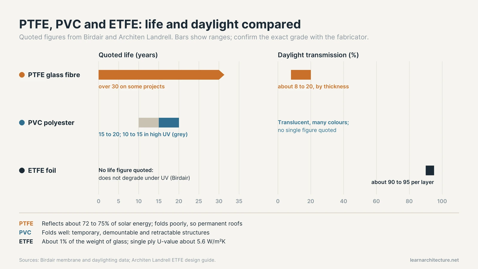
A woven glass fibre base cloth coated with PTFE (polytetrafluoroethylene) is the long-life option. Birdair, the US membrane contractor, says it has the longest proven lifespan of any membrane, with project lives in some cases exceeding 30 years, and that it works from arctic to desert climates. In Birdair’s daylighting data, PTFE glass fibre reflects about 72 to 75 percent of solar energy while letting through roughly 8 to 20 percent of daylight, depending on thickness. The trade-off is stiffness: glass fibre does not like repeated folding, so PTFE suits permanent roofs rather than deployable ones.
PVC-Coated Polyester
Polyester cloth coated with PVC (polyvinyl chloride) is the most common membrane for flexible structures, according to Birdair. With a protective acrylic or PVDF top coat, it has a design life of about 15 to 20 years, dropping to about 10 to 15 years in high-UV regions such as Florida or the US Southwest. It comes in many colours and folds well, which makes it the default for temporary, demountable and retractable work.
ETFE Foil
ETFE (ethylene tetrafluoroethylene) is a clear polymer film rather than a coated fabric. The UK fabricator Architen Landrell explains in its ETFE design guide that it is used either as a single layer supported by cables or as multi-layer cushions held in aluminium extrusions and kept pressurised by a small inflation unit. A single medium-weight layer transmits roughly 90 to 95 percent of visible light, and the firm puts its weight at about 1 percent of glass. Insulation is the weak point: a single ply has a U-value of about 5.6 W/m²K, so cushions with extra layers of air are used where heat loss matters.
Material Comparison at a Glance
The table below gathers the figures quoted above from Birdair and Architen Landrell. Use it to shortlist; confirm the exact grade with the fabricator.
| Property | PTFE glass fibre | PVC polyester | ETFE foil |
|---|---|---|---|
| Form | Coated woven fabric | Coated woven fabric | Extruded film, single ply or cushion |
| Quoted life | Over 30 years on some projects | About 15 to 20 years (10 to 15 in high UV) | Does not degrade under UV (Birdair) |
| Light | About 8 to 20 percent daylight | Translucent, many colours | About 90 to 95 percent per layer |
| Folding | Poor; permanent roofs | Good; temporary and retractable | Cushions fixed in frames |
| Typical use | Stadiums, airports, long-life roofs | Event tents, canopies, sports halls | Atria, facades, glass replacement |
Form Finding: How the Shape Is Found
You cannot simply draw a tensile roof and then ask an engineer to make it stand. Only certain shapes are in equilibrium under a given pretension, so the geometry has to be found rather than chosen. Frei Otto built his career on this. The Pritzker Prize jury’s biography of Frei Otto, the 2015 laureate, records that he built complex physical models from the 1950s onward to test tensile shapes, and that even when his engineers adopted computers, the input data came from those form-finding models. His later research also examined the structural properties of soap bubbles, bamboo and crustaceans.
Today the same search runs in software, which iterates toward a surface that is in equilibrium for a chosen pretension and set of boundaries. Our introduction to form finding in architecture traces that line from Otto’s models to computation.
Once the form is fixed, it has to be cut from flat cloth, and that step is where many details are decided.
📐 Technical Note
A double-curved membrane is assembled from flat strips cut along predefined lines, typically geodesics. Stimpfle explains that strip width is set by the allowable distortion and by the roll width of the material. Typical joints include welded seams, clamping joints, cable cuffs and clamped border lines, the last being typical for PTFE glass fibre. Every seam is visible from below, so the cutting pattern is an architectural drawing as much as a fabrication one.
Iconic Tensile Structure Examples
Three roofs show the system at very different scales and with different materials. Each also carries a lesson about cost, programme or performance.
Munich Olympic Park Roof (1972), Munich, Germany
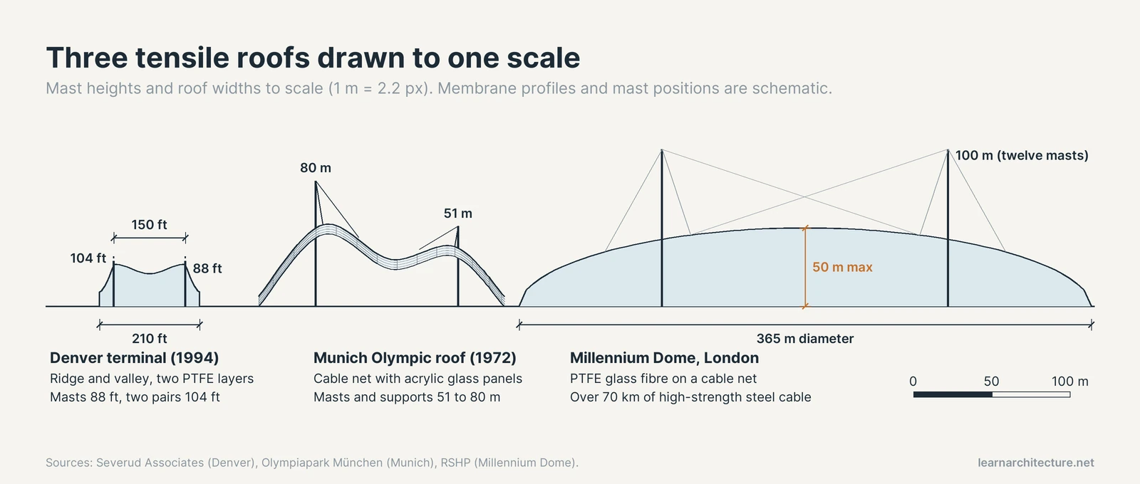
Area: 78,000 m² | Masts and supports: 51 to 80 m | Designers: Behnisch & Partner with Frei Otto and Jörg Schlaich
The official Olympiapark tent roof page describes a steel cable net suspended from pylons and supports between 51 and 80 metres high, clad in acrylic glass panels and covering 78,000 square metres over the Olympic Stadium, Olympic Hall and swimming hall. Günter Behnisch’s Stuttgart group won the 1967 competition with a scheme that set the venues into earth hollows under a transparent canopy; on 13 October 1967, 17 of the 19 jury members backed it. Behnisch then brought in Frei Otto and the engineer Jörg Schlaich to make it buildable.
The roof is a set of saddle-shaped cable net surfaces framed by edge cables and hung from masts. Schlaich Bergermann Partner, the firm Schlaich later co-founded, credits the project with the first iterative computer application for this type of problem and with a revival of cast steel nodes in architecture. It was also, the park’s own page admits, a costly sensation, and its progress was watched internationally.
Denver International Airport, Jeppesen Terminal (1994), Denver, USA
Roof membrane: 375,000 sq ft | Mast heights: 88 to 104 ft | Architect: Fentress Architects; engineer: Severud Associates
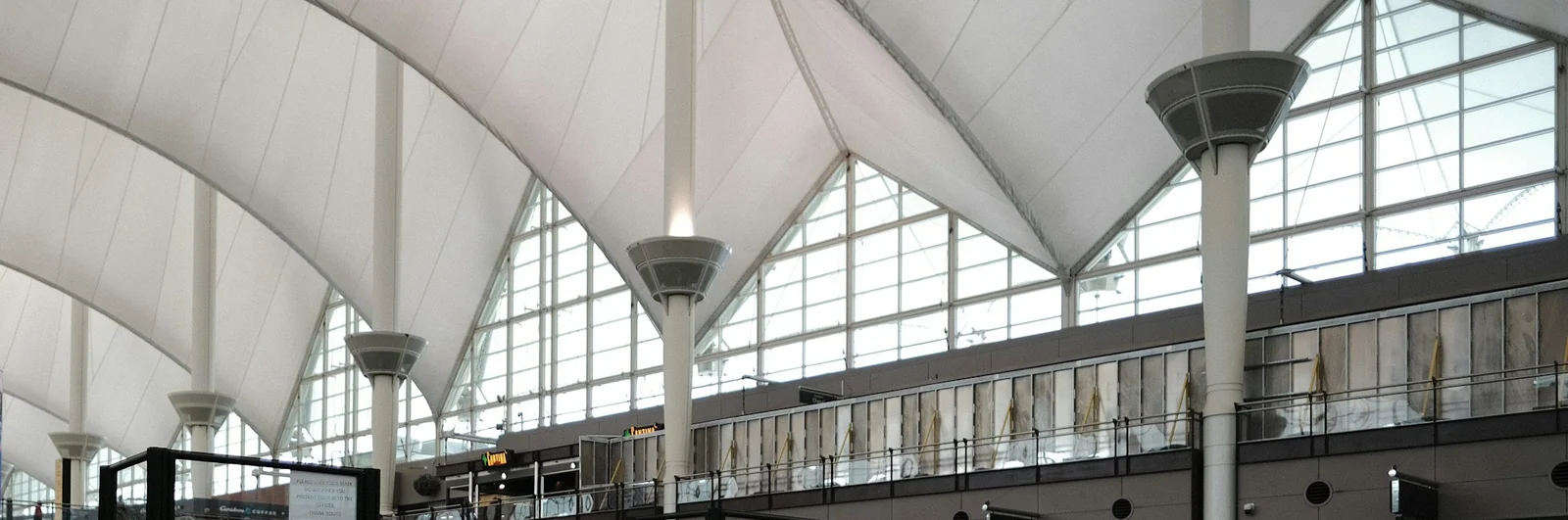
Severud Associates’ Jeppesen Terminal roof case study describes a ridge and valley membrane over the Great Hall. Pairs of masts spaced 150 ft apart across the hall and 60 ft along it create the peaks; most masts are 88 ft tall, with two pairs rising to 104 ft. Valley cables arch across the 210 ft width between the mast pairs. The PTFE-coated glass fibre roof has two layers: the outer one carries snow and wind, while the inner one forms an insulating air gap and diffuses light.
Birdair, which built the membrane, gives a figure of 375,000 sq ft for the terminal roof plus another 75,000 sq ft over the curbside canopies, and dates completion to 1994. Snow drove much of the engineering: Severud tested scale models in a boundary layer wind tunnel and a water flume snow simulator, then used the drift patterns to build dozens of load cases for its non-linear analysis. The peaks echo the Rocky Mountains, but the double skin exists for acoustics and Denver’s climate, not imagery.
🔢 Quick Numbers
- Munich Olympic roof: 78,000 m² of cable net and acrylic glass (Olympiapark München)
- Denver terminal: almost one million sq ft of fabric across the whole project (Severud Associates)
- Millennium Dome: 365 m diameter, twelve 100 m masts, more than 70 km of cable (RSHP)
- Birdair’s 1972 pavilion at the University of La Verne, California, still uses its original PTFE roof (Birdair)
Millennium Dome, London, UK
Diameter: 365 m | Masts: twelve at 100 m | Architect: Richard Rogers Partnership; engineer: Buro Happold
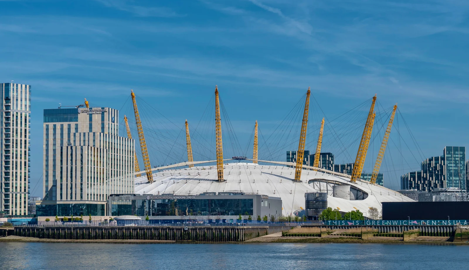
The RSHP project page gives the key dimensions: 365 metres in diameter, a 1,000 metre circumference, a maximum height of 50 metres and 100,000 square metres of enclosed floor. Twelve 100 metre steel masts hold more than 70 kilometres of high-strength steel cable, which in turn support a PTFE-coated glass fibre roof. Buro Happold describes the fabric as 1 mm thick, with an inner lining that reduces solar gain and absorbs sound and condensation.
Speed shaped the choice of a tensile cable net. Buro Happold notes that the Greenwich Peninsula was only selected in 1996 and that the Dome had to be finished by 1998 so the Millennium Experience exhibitions could be installed in time. RSHP reports that the structure was delivered within fifteen months and under budget, at £43 million for groundworks, perimeter wall, masts, cable net and roof fabric. The building itself was a success; the exhibition inside, which was not the architects’ brief, was savaged by the press. The flexible enclosure later became The O2 entertainment venue.
🏗️ Real-World Example
Velodrome (Abuja, Nigeria): Stimpfle records that this membrane roof failed in a thunderstorm and was rebuilt as a redundant system, with a primary cable net designed to remain stable even if one or more membrane panels are damaged in future. It is a useful reminder that a tensile roof should not depend on every panel staying intact.
Other airport and stadium roofs follow the same logic at smaller scale. Our roundup of impressive airport design places Denver among its peers, and the history of stadium architecture shows how lightweight roofs changed the way stands are covered.
Advantages and Limits of Tensile Structures
The appeal is easy to list. Large column-free spans for very little material, fast prefabricated erection, daylight through a translucent skin, and a shape that reads clearly from far away. Buro Happold says the Millennium Dome went from initial concept to execution in only two years, and that the deadline made a tensile structure the logical solution.
The limits are just as real. Foundations and anchors work harder because every cable force ends up in the ground. Single-layer membranes insulate poorly, so heated buildings need double skins or cushions, as Denver shows. Membranes also have finite lives, from roughly 10 to 20 years for PVC to 30-plus for PTFE, so a facility owner must plan for replacement in a way that a concrete roof owner usually does not.
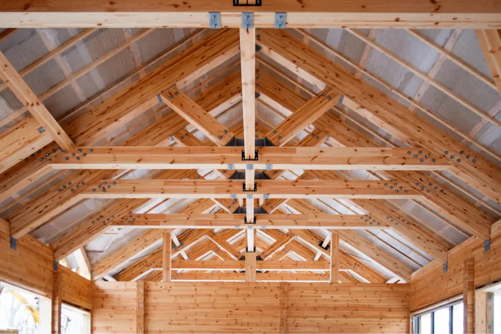
Conventional steel trusses remain the alternative for many long-span roofs. If you want to compare the two approaches, our explainer on how a truss works covers the compression-and-tension frame that a tensile roof avoids.
The Bigger Picture
A tensile roof turns structure into a negotiation between shape, prestress and material, where the designer cannot pick one without accepting the other two. Munich, Denver and Greenwich each show that negotiation at full scale, and each paid for its lightness somewhere: in Munich’s cost, in Denver’s elaborate snow studies, in the Dome’s finite fabric life. The most material-efficient roof is rarely the simplest one to design, and that is exactly why the best tensile structures still read as engineering made visible.








Leave a comment