


Table of Contents Show
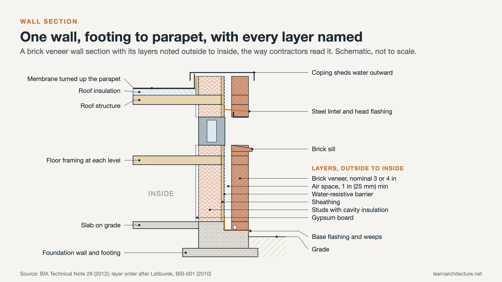
A wall section is a vertical cut through one exterior wall, drawn from the footing to the roof edge at a large scale, that names every layer of the assembly and shows how those layers meet the floors, openings and roof. It sits between the building section and the detail sheets, and it is the drawing contractors use to price and build the envelope.
Most students meet the wall section as the sheet that looks like a building section cropped to one thin strip. That impression undersells it. A general section drawing explains space: ceiling heights, level changes, how rooms stack. A wall section explains construction. It answers where the water goes, where the air stops, what holds the cladding up and what happens at every floor line. If you can draw one well, you understand the building; if you cannot, the gaps show up on site.
What a Wall Section Shows (and What It Leaves to Details)
The job of a wall section is continuity. One drawing tracks a single wall type through its full height, so you can see the same layers pass the foundation, the ground floor slab, each intermediate floor, the window heads and sills, and finally the parapet or eave. Along the way it records:
- The structure: footing, foundation wall, studs or block, slab edges, beams and the roof structure.
- The enclosure layers: cladding, cavity or air space, insulation, sheathing, water-resistive barrier, air barrier and interior finish.
- Vertical dimensions: finished floor levels, top of plate or top of slab, window head and sill heights, parapet height.
- Callouts: bubbles that point to enlarged details for anything too small to resolve at wall section scale.
What it does not do is solve every junction. A flashing lap, a sealant joint or a window jamb needs a detail at a larger scale. Think of the wall section as the index for those details: it proves the layers line up across the whole height and sends you to the enlarged drawing where they get complicated.
Wall section vs building section vs detailed wall section
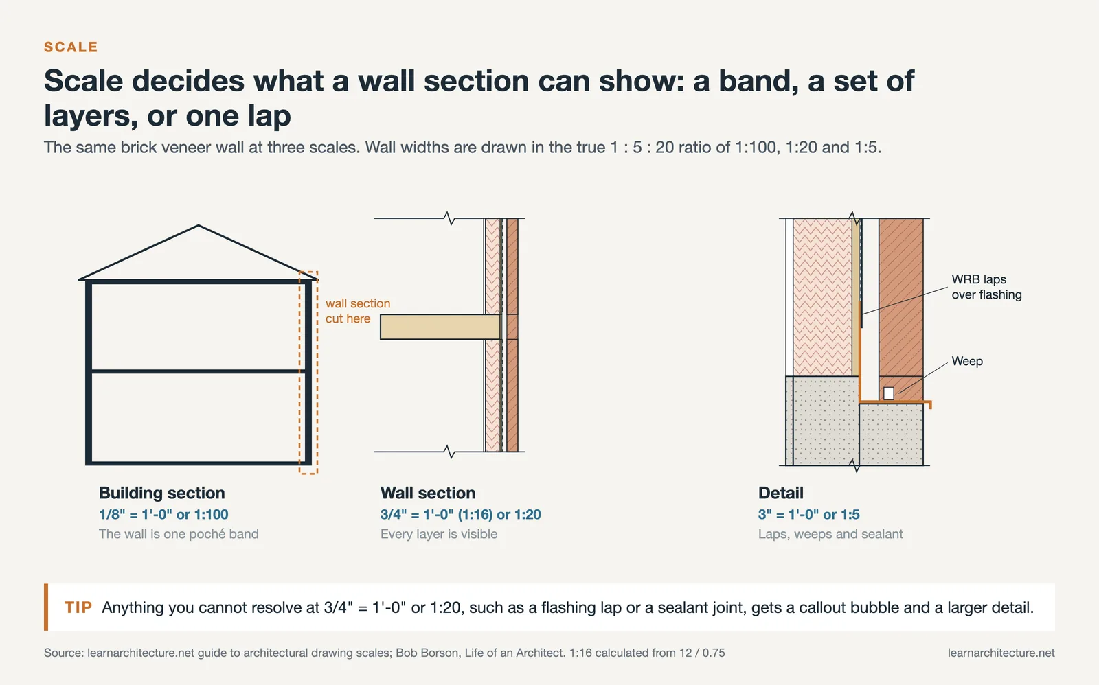
Offices use the terms loosely, so it helps to separate them by scale and purpose. The table below reflects common US and UK practice; your firm standard may differ.
| Drawing | Typical scale | What it answers |
|---|---|---|
| Building section | 1/8″ = 1′-0″ or 1:100 | Room heights, levels, overall form |
| Wall section | 3/4″ = 1′-0″ or 1:20 | Every layer of one wall, footing to roof |
| Detail (head, sill, parapet) | 1″ or 3″ = 1′-0″, 1:10 or 1:5 | Laps, fasteners, sealant, tolerances |
A “detailed wall section” usually means a wall section drawn with enough annotation that some junctions are resolved on the section itself rather than called out, which is common on small residential sets where the sheet count has to stay low.
Scale, Sheet and Where the Wall Section Lives in a Set
In US offices the default scale is 3/4 inch to the foot, which is exactly 1:16. Metric offices use 1:20, and the site’s guide to architectural drawing scales explains why anything smaller than 1:20 stops being able to separate insulation, cavity, membrane and finish at print size. On taller buildings the full wall will not fit on one sheet at that scale, so the section is broken with break lines and repeated floors are shown once with a note such as “typical floors 3 to 8”.
📐 Technical Note
The United States National CAD Standard, published by the National Institute of Building Sciences, numbers sheets by type: building sections belong on the 3-series, the 4-series holds large-scale views of individual areas, and the NCS notes there are very few cases where wall sections would move to the 4-series. In practice that puts most wall sections on sheets numbered A-3xx. Check your client or firm standard, since sequence numbers are user-defined.
The NCS frequently asked questions page gives the reasoning: sections of stairs and elevators can stay on 3-series sheets unless there is a reason to pull them to the 4-series. Whatever the numbering, the wall section must be referenced from the building sections and elevations with a section mark, so a reader on the elevation can find the cut.
How to Read a Wall Section Detail
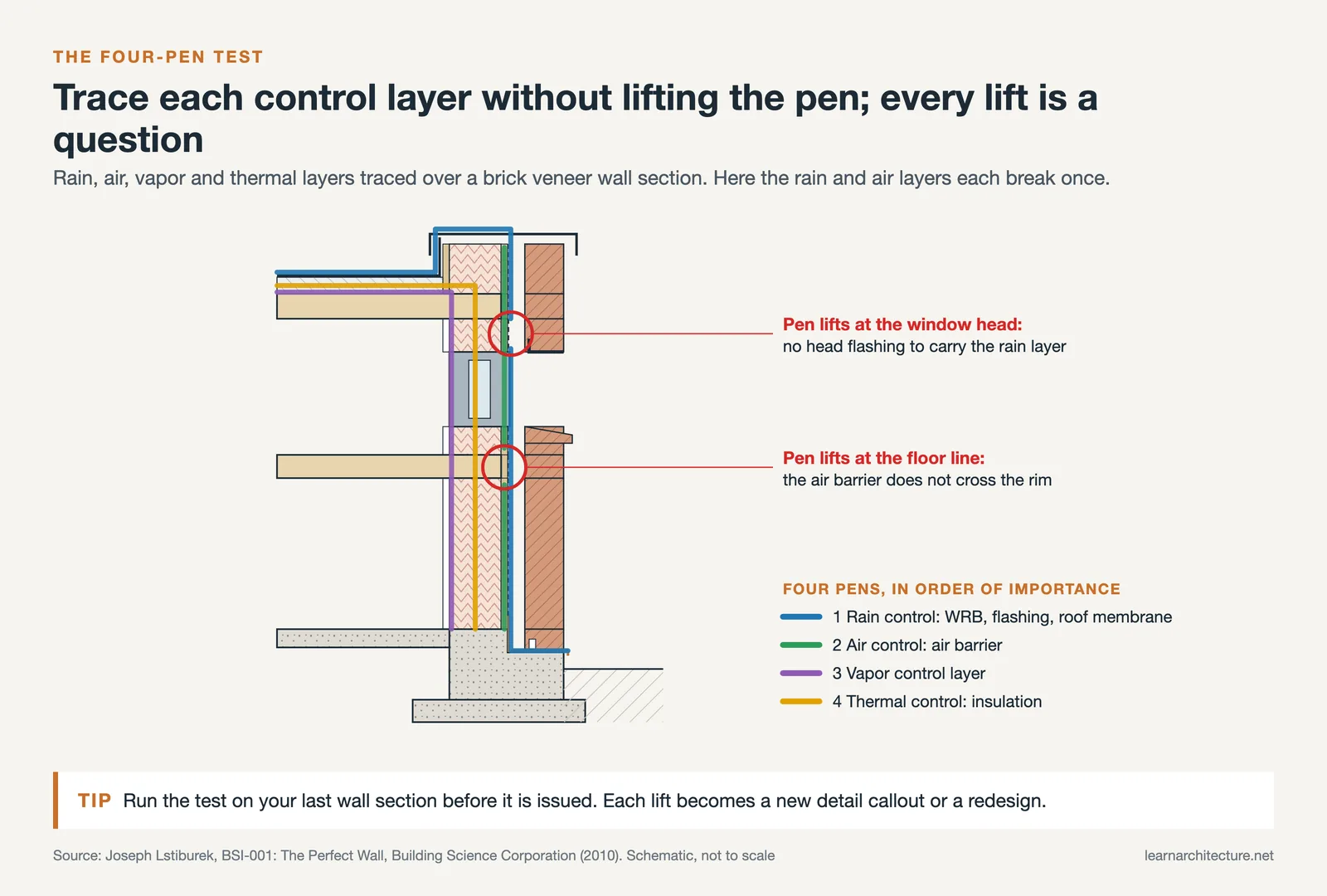
Reading a wall section is easier if you stop scanning the notes and instead trace the control layers. Joseph Lstiburek of Building Science Corporation set out the order in “BSI-001: The Perfect Wall” (2010): a rain control layer, an air control layer, a vapor control layer and a thermal control layer, in that order of importance, ideally all outside the structure.
The four-pen test
Print the wall section and take four colored pens. Trace the rain control layer (the water-resistive barrier or drained cavity) from the base flashing to the roof membrane without lifting the pen. Do the same with the air barrier, the vapor control layer and the insulation. Every place you have to lift the pen is a question for the architect: a slab edge the air barrier does not cross, a window head where the flashing stops, a parapet where the insulation dies at the roof deck. This is the most useful five minutes you can spend with any wall section detail, because it turns a crowded drawing into four lines you can check.
Reading the notes and hatches
Notes on a wall section follow a leader-and-label convention: the leader touches the layer, the label names the material and often its thickness or specification number. Materials that are cut are hatched; materials seen beyond are shown in outline. If you are unsure which pattern means rigid insulation and which means batt, the site’s guide to hatch patterns and poché covers the standard set. Heavier line weight marks the cut, which is why a well drawn wall section reads from across the room even before you look at the words.
💡 Pro Tip
Write the material notes in the same order as the layers, outside to inside, and stack them in one column on the exterior side of the wall. Contractors read the column like a specification, and a reviewer can spot a missing layer in seconds when the list and the drawing disagree.
How to Draw a Wall Section, Step by Step
The sequence below works for hand drafting, CAD or a section view in BIM. In BIM the software cuts the model for you, but you still need to decide where the cut goes, what to annotate and where to break the drawing.
- Choose the cut. Cut through the most typical condition of one wall type, ideally through a window so the head and sill appear. Draw a separate wall section for each wall type.
- Set the datums. Draw horizontal lines for top of footing, finished floor at each level, top of plate or slab, and top of parapet or ridge. Label each with its elevation.
- Draw the structure. Footing, foundation wall, floor framing or slab edges, wall framing or block, roof structure. Keep these heavy, because they are cut.
- Add the enclosure layers outside to inside. Cladding, air space, water-resistive barrier, sheathing, insulation, vapor control, interior finish. Draw real thicknesses, not a single line for a 2 inch (51 mm) board.
- Resolve the transitions. Foundation to wall, each floor line, window head and sill, wall to roof. Draw flashing where the layers change.
- Annotate and dimension. Material notes, vertical dimensions, and callout bubbles for every junction you will detail at larger scale.
- Run the pen test. Trace all four control layers before issuing the sheet.
Line hierarchy matters more on a wall section than on almost any other sheet, because everything is packed into a narrow strip. The guide to architectural line weights sets out the cut, seen and beyond hierarchy that keeps it legible.
Common Wall Section Types and What Each One Must Show
Different wall systems have different failure points, so each type of wall section has its own checklist. Three types cover most student and early-career work.
Brick wall section (anchored veneer on studs)
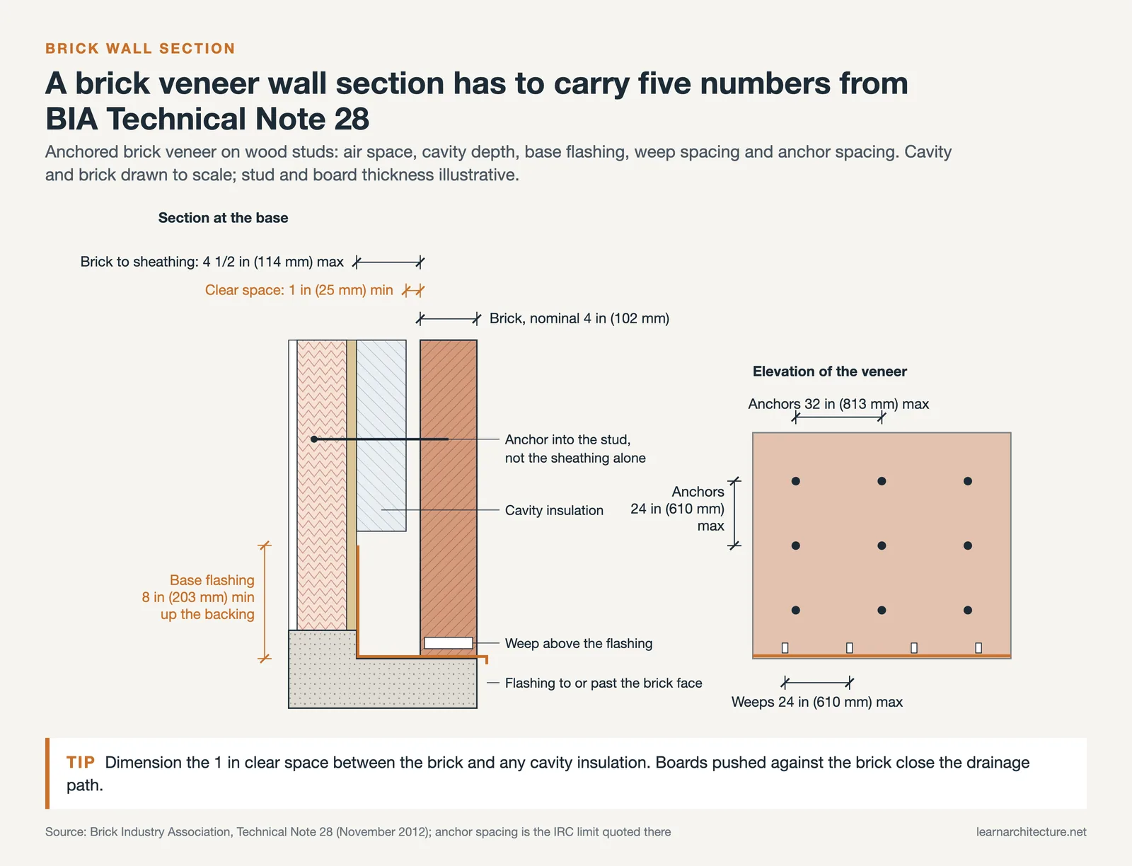
A brick wall section in residential and light commercial work is usually anchored veneer: a nominal 3 or 4 inch (76 or 102 mm) brick wythe tied to a wood or steel stud backup across an air space. The Brick Industry Association’s Technical Note 28 on brick veneer and wood stud walls (2012) lists what the section needs to show:
- A minimum 1 inch (25 mm) air space behind the brick, and no more than 4 1/2 inches (114 mm) between the back of brick and the sheathing unless the anchors are specifically designed for it.
- Base flashing above grade, extended at least 8 inches (203 mm) up the backing and out to or beyond the face of the brick.
- Weeps above every flashing: open head joints at no more than 24 inches (610 mm) on center, or wicks and tubes at no more than 16 inches (405 mm).
- Anchors at no more than 32 inches (813 mm) horizontally and 24 inches (610 mm) vertically under the IRC, secured to the studs and not to the sheathing alone.
The same note records that a nominal 4 inch brick wythe alone gives a 1 hour fire resistance rating for the exterior face, and that brick veneer on wood studs routinely reaches 2 hour ratings with fire-rated gypsum inside. Behind the veneer, the 2021 International Residential Code, Section R703.2, requires at least one layer of water-resistive barrier over the studs or sheathing, continuous to the top of the wall. Your local jurisdiction may have amended these figures, so confirm the adopted edition.
⚠️ Common Mistake to Avoid
Drawing the air space as a clear gap and then filling it with continuous insulation that touches the brick. BIA Technical Note 28 asks for 1 inch (25 mm) between the back of the brick and the face of any insulation placed in the cavity. Show and dimension that clear space, or the drainage path the whole brick wall section depends on disappears.
CMU wall section
A CMU wall section starts with the module. The Concrete Masonry and Hardscapes Association’s CMU-TEC-001 technical note explains that units have nominal face dimensions of 8 by 16 inches (203 by 406 mm), and that specified dimensions are typically 3/8 inch (9.5 mm) less than nominal so the 8 inch module holds with 3/8 inch mortar joints. A nominal 8 inch block is therefore drawn 7 5/8 inches thick. On the section, dimension heights in whole courses (8 inch increments) wherever you can, and set window heads and sills to a course line so the mason is not cutting block.
The section also has to say which cells are grouted and reinforced, where the bond beam runs at the top of the wall and at floor bearing, and where the insulation sits. Exterior insulation keeps the block inside the thermal envelope; interior furring with insulation leaves the block exposed to outdoor temperature and moves the dew point. For single-wythe block, show the water management strategy explicitly, because block alone is not a rain barrier.
Curtain wall section
A curtain wall section reads differently because the cladding hangs from the structure rather than sitting on it. The section cuts through a vertical mullion and shows the anchors at each slab edge, the horizontal transoms, the vision glass and the opaque spandrel panel in front of the floor zone. The critical areas are the slab edge, where the gap between slab and curtain wall must be firestopped and the spandrel insulated, and the stack joint, where the system takes up floor-to-floor movement. Because most of this depends on the manufacturer’s system, the architect’s curtain wall section usually sets the layout, the sightlines and the performance requirements, and the shop drawings resolve the extrusions.
Where the Wall Meets the Roof: the Wall/Roof Section Detail
The top of the wall is where the water and air layers of the wall have to hand over to those of the roof, which is why many offices draw a combined wall/roof section detail at 1 inch to the foot or 1:10. On a flat roof this is the parapet: the roof membrane turns up the inside face, the wall air barrier has to connect to the roof air barrier across the top of the wall, and the coping has to shed water outward. The site’s article on parapet walls and roof details covers the parapet types in depth. On a pitched roof the equivalent junction is the eave, where the wall insulation should meet the roof insulation without a gap at the top plate.
Run the pen test here twice. A wall that passes on its own and a roof that passes on its own often fail at the junction, because two different consultants, two different trades and two different sheets meet at one line.
What This Means for Your Next Project
A wall section earns its place in the set by being the one drawing where every layer has to agree with every other. Draw it early, not at the end of construction documents, because it exposes problems (insufficient cavity depth, a slab edge the insulation cannot cover, a window that lands between courses) while they are still cheap to fix.
Your Next Step: Take the last wall section you drew, print it at scale, and run the four-pen test on it. Every place you lift the pen becomes either a new detail callout or a redesign.
Code figures in this article refer to the 2021 IRC and to industry technical notes. Building codes are adopted and amended locally, so check the edition in force in your jurisdiction and have the envelope reviewed by a licensed professional.
Frequently Asked Questions
What scale is a wall section drawn at?
In US practice a wall section is usually drawn at 3/4 inch = 1′-0″, which is 1:16. Metric offices use 1:20. Details called out from the wall section are drawn larger, typically 1 or 3 inches to the foot, or 1:10 and 1:5.
What is the difference between a wall section and a detail?
A wall section shows one wall type over its full height, from footing to roof, so you can check that the layers are continuous. A detail enlarges one junction, such as a window head or parapet, to show laps, fasteners and sealant joints that are too small to read on the wall section.
How many wall sections does a project need?
One for each distinct wall type, plus extra sections where a typical wall meets an unusual condition such as a change in grade, a canopy or a different roof. A small house may need two or three; a building with brick, curtain wall and metal panel may need a dozen.
What should be labeled on a wall section?
Every layer from outside to inside with its material and thickness, the floor and roof elevations, window head and sill heights, and callout bubbles for each enlarged detail. Structural members should carry the size shown on the structural drawings, not a separate one.











Leave a comment