


Table of Contents Show
A massing diagram is a simple three-dimensional drawing that shows a building as solid volumes, without windows, materials or detail, so you can judge its overall size, shape and placement on the site. In early design it is used to test options against zoning limits, sunlight and context before any plan is fixed.
Most first-year students meet massing through a clay or foam block model, then lose the habit once they move into software and start drawing walls too early. That is a mistake. The massing stage is where the big decisions get made: how tall, how deep, where the courtyard goes, which corner steps down to the neighbor. This guide covers what a massing diagram in architecture actually shows, the zoning numbers that shape it, a step-by-step method for a massing study, and how to present the result so a jury reads the logic in seconds. For the wider family of drawings it belongs to, see our reference to architectural diagram types.
What Is a Massing Diagram in Architecture?
Building massing is the overall three-dimensional form of a building: its volumes, heights and how they sit together. A massing diagram represents that form as plain blocks, usually in axonometric or aerial view, with the surrounding buildings shown in a lighter tone for context. It is deliberately abstract. The moment you add mullions or textures, the reader starts judging facade design instead of form.
It helps to separate two related terms. A massing study is the process: building many quick volumes to compare options. A massing diagram is the product: a clean drawing that explains the chosen form and, often, how it was derived. You do the study for yourself and draw the diagram for someone else.
Massing sits between two earlier diagrams. A bubble diagram tells you which spaces need to be near each other, and a zoning diagram sorts them into public, private and service areas in plan. Massing turns those areas into volume: it decides which zone goes up, which stays low, and how the pieces stack.
📌 Did You Know?
Some of the most influential massing drawings ever made had no building program at all. In 1922, architect Harvey Wiley Corbett commissioned Hugh Ferriss to draw four stages showing how New York’s 1916 zoning law shaped the maximum building envelope. Those drawings later appeared in Ferriss’s 1929 book The Metropolis of Tomorrow.
Start With the Envelope: The Numbers Behind Building Massing
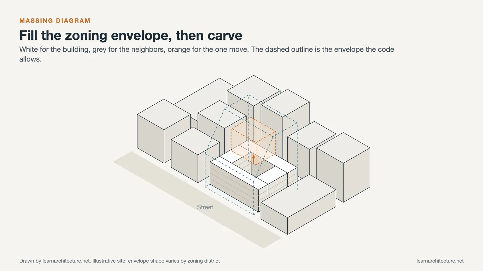
A massing study is not free sculpture. On a real site, zoning sets an invisible container, and your first mass is usually that container. New York City’s Glossary of Zoning Terms (last updated 2021) defines the key ideas clearly, and most zoning codes use similar concepts under different names:

- Building envelope: the maximum three-dimensional space on a zoning lot within which a structure can be built, as permitted by height, setback and yard controls.
- Floor area ratio (FAR): the ratio of total building floor area to the area of the zoning lot. Multiplying the district’s FAR by the lot area gives the maximum floor area.
- Lot coverage: the portion of the lot covered by a building when viewed from above.
- Sky exposure plane: a virtual sloping plane that starts at a set height above the street line and rises inward over the lot; a building may not penetrate it, which protects light and air at street level.
These two controls pull in different directions. The envelope tells you the largest shape you may build. FAR tells you how much floor area you may put inside it. When the envelope can hold more floor area than the FAR permits, that gap is exactly where massing design happens: you decide which parts of the envelope to occupy.
📐 Technical Note
The NYC glossary gives a simple example: on a 10,000 square foot (about 929 m²) zoning lot with a maximum FAR of 1.0, floor area cannot exceed 10,000 square feet. The same lot at FAR 2.0 allows 20,000 square feet (about 1,858 m²), whether as two full floors or four floors covering half the lot. Definitions of what counts as floor area vary by jurisdiction, so check your local code before relying on any number.
For a studio project without a real zoning district, your tutor may give you an FAR, a height limit and setbacks. Treat them the same way: build the envelope first, then calculate the floor area target, then carve.
How to Develop a Massing Study Step by Step
The method below works by hand, with foam blocks, or in any 3D program. Keep every option at the same scale and viewing angle so they can be compared.

1. Model the Site and the Envelope
Model the plot, the neighboring buildings as simple blocks, and the street widths. Then extrude the plot to the height limit, cut back the setbacks, and slice off anything above the sky exposure plane if one applies. This translucent volume is your envelope. Keep it on its own layer so you can switch it on and off.
2. Turn the Program Into Volumes
Take the area schedule from your brief and turn each major zone into a block of the right floor area. A 600 m² (about 6,460 sq ft) library zone might be one block two floors tall or one long single-story bar. Color blocks by zone, using the same colors as your zoning diagram, so the link between plan logic and form stays visible.
3. Test Several Options
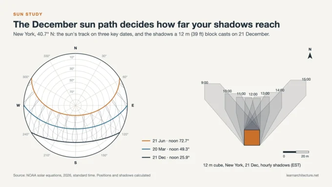
Arrange the blocks inside the envelope in at least three fundamentally different ways: a tall slab, a low courtyard type, a stepped form, a cluster of separate volumes. Do not refine any of them yet. For each option, check the shadow it casts on the street and its neighbors; our roundup of sun-path and shadow study apps lists tools that can run this in minutes.
💡 Pro Tip
Build a quick physical version of your two strongest options, even from cardboard or foam. Turning a block in your hand under a desk lamp reveals shadow and proportion problems that a screen view hides, and juries respond well to seeing the study models next to the final diagram.
Physical and digital studies support each other; our article on concept models explains when each is more useful.
4. Check the Floor Area in Software
Once an option looks promising, verify it against the FAR target. Each program has a direct way to do this.
- Revit: create a mass, then use Mass Floors from the Modify | Mass tab and select each level that needs a floor. Revit only creates mass floors where the mass intersects a level, and each mass floor reports its own area, perimeter and volume and can be given a usage, which you can then schedule.
- Rhino: run Contour on your volumes with the interval set to your floor-to-floor height. It creates planar curves by intersecting evenly spaced planes with the objects. Then select the closed curves and use the Area command, which adds up the total when several objects are selected.
- SketchUp: draw the footprint and use Push/Pull (shortcut P), typing the exact height in the Measurements box. Pressing Ctrl on Windows or Option on macOS before double-clicking stacks an identical extrusion on top, which is a fast way to add floors of equal height.
Compare the total with your target and adjust. If you are over, remove a block from the least useful part of the envelope rather than shrinking everything evenly. Massing is a series of choices about where floor area goes, not a uniform scaling exercise.
How to Present Architectural Massing Diagrams
A final massing diagram usually explains how the form was reached, as a short sequence of steps. The strongest architectural massing diagrams follow a few conventions.
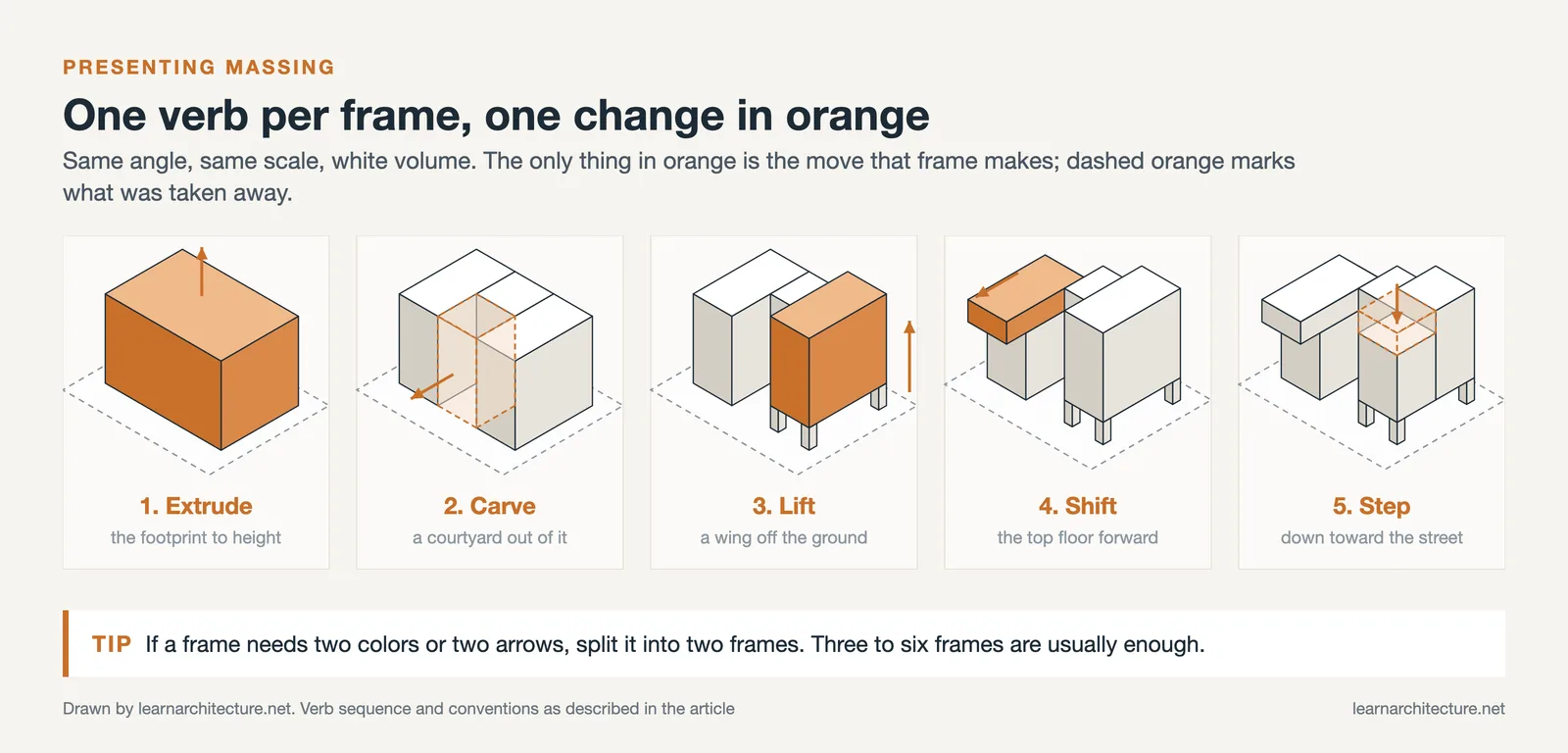
Use a Sequence of Verbs
Show three to six small axonometric frames, each labeled with a single verb: extrude, carve, lift, shift, split, step. Each frame changes one thing from the previous one. The reader should be able to follow the logic without reading a paragraph.
Keep One Angle, One Scale, One Accent Color
Every frame uses the same viewing angle and scale. The volume is white or light gray, context buildings are a lighter or dashed tone, and the single change in each frame is picked out in one accent color. Arrows show the direction of each move.
Include Context and a Ground Plane
A mass floating in white space tells the reader nothing about why it has that shape. Show at least the immediate neighbors and the street edge so moves like stepping down or pulling back read as responses to something real. On a board, the sequence usually sits near the site plan; our presentation board tips cover layout and hierarchy.
Wrapping Up
A massing diagram earns its place on the board when it shows a decision, not just a shape. Build the envelope from real limits, test options quickly, verify the numbers, and then draw the sequence that explains why the final form wins.
Quick Recap:
- Start every massing study with the zoning envelope and the FAR target.
- Test at least three different arrangements at the same scale before refining one.
- Check floor area with Mass Floors in Revit, Contour and Area in Rhino, or Push/Pull in SketchUp.
- Present the result as a short verb sequence with one angle, one scale and one accent color.
Frequently Asked Questions
What is the difference between a massing diagram and a massing model?
A massing model is the three-dimensional object, physical or digital, that you use to study form. A massing diagram is a drawing made from that model to explain the chosen form, often as a sequence of steps with labels and arrows.
What should a massing diagram include?
Plain volumes of the building, the neighboring buildings in a lighter tone, the ground plane or site edge, and simple labels or arrows explaining each move. Windows, materials and detailed landscape usually stay out.
What software is best for a massing study in architecture?
SketchUp is fast for blocking out volumes, Rhino gives more control over complex forms and slicing, and Revit connects mass floors directly to area schedules. Many students block out in SketchUp or Rhino and move to Revit once the form settles.
How does FAR affect building massing?
FAR sets the maximum total floor area, while the building envelope sets the maximum shape. When the envelope can hold more than the permitted floor area, massing decides which parts of the envelope to fill and which to leave open.








Leave a comment