


Table of Contents Show
A stair section is a vertical cut through a staircase that shows how it climbs from one floor to the next: the risers and treads, the stringer or waist slab that carries them, the landings, the handrail and guard, and the headroom above. Builders use it to check heights, structure and fit before anything is made.
A plan tells you where the stair sits and which way it turns. Only the section tells you whether 19 risers really fit between two finished floors, whether a tall person clears the beam above the fifth step, and what is holding the treads up. That is why a stair often gets its own sheet in a construction set, and why the drawing rewards a slow, methodical layout. The guide below walks through the parts you draw, a step-by-step method, three typical details in concrete, steel and timber, and real drawings from the Historic American Buildings Survey and from working architects.
What Is a Stair Section?
A stair section is drawn by slicing the staircase along its direction of travel, usually through the middle of a flight, and looking at the cut face. Everything the cutting plane passes through, such as the waist slab, the treads, the landing and the floor slabs, is drawn with a heavy line or a hatch. Everything seen beyond the cut, such as the far flight or the balusters, is drawn lighter.
The section sits between the general building section and the large-scale details. If you need a refresher on how cut planes work in any building drawing, our guide to understanding section drawings covers full, half and offset sections. The same rules apply here, to one element that has to obey strict geometry.
Plan, Elevation and Section Compared
The three drawings describe the same stair but answer different questions. Reading them together is the only way to check a stair properly.
| Drawing | What it shows | What it cannot show |
|---|---|---|
| Stair plan | Width, tread count, direction, landing size, cut line | Riser heights, headroom, structure |
| Stair elevation | Balusters, handrail profile, finishes seen from the side | Slab thickness, what is inside the stringer |
| Stair section | Rise, going, pitch, levels, headroom, structure | Width and turns, unless several cuts are drawn |
The drawing below shows why the two are inseparable. It is a winder staircase in reinforced concrete with brick steps, posted by @17archstudio. The plans at the top carry three cut lines, A-A, B-B and C-C, and the three sections underneath show what each cut reveals. The steps are numbered 01 to 33 on both plans and sections, so any step can be traced from one drawing to the other.

What a Staircase Section Shows
Every staircase section, whatever the material, carries the same set of parts. Learning to name them is the first step to drawing them, and it is also how you check someone else’s drawing.
Stringer or Waist Slab
The stringer is the inclined member that carries the treads. In timber and steel stairs it is a separate board or channel on each side; a closed stringer hides the tread ends, while an open (cut) stringer follows the step profile. In a cast concrete stair there is no stringer at all. The treads sit on a sloping waist slab, and its thickness, measured at right angles to the slope, is what the section has to dimension.
Treads, Risers and Nosing
The tread is the horizontal surface you step on and the riser is the vertical face between treads. The nosing is the front edge of the tread, which often projects past the riser below. In section, the line joining all the nosings is the pitch line, and it controls the handrail height and the headroom measurement.
Landings
A landing breaks a flight or turns it. In section, draw the landing with its full structure, because it usually carries the load of two flights and is where most coordination errors appear: a landing beam that clashes with a door head, or a landing level that does not match a mezzanine.
The Headroom Line
The headroom line is a line drawn parallel to the pitch line at the required clear height, used to check that no beam, slab edge or soffit cuts into it. Under the International Residential Code, section R311.7.2 sets the headroom at not less than 6 feet 8 inches (2032 mm), measured vertically from the sloped line adjoining the tread nosings, according to the 2021 IRC chapter 3. Riser, tread, width and landing limits vary by code and are listed in our article on minimum stair dimensions.
Handrail and Guard
The handrail is what you hold, and the guard is the barrier that stops a fall from the open side. They are often one assembly in a house but separate in commercial work, where a wall-mounted handrail runs on the wall side and a guard with balusters or panels runs on the open side. The section should show both heights, the handrail extension past the top and bottom risers, and the fixing.
The Structure Behind the Stair
The section must show what the stair hangs from and lands on: floor slabs, trimmer beams, footings, the wall it is anchored to. A beautifully drawn flight that stops in mid-air at the top is the clearest sign of a drawing nobody checked with the structural engineer.
How to Draw a Stair Section Step by Step
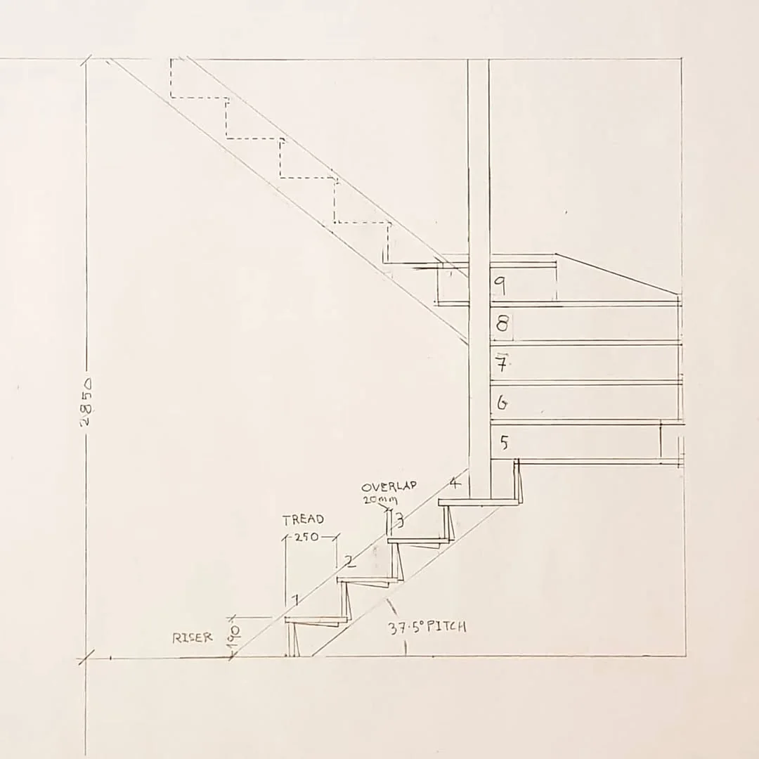
The method below works by hand or in CAD. The example is a hand-drawn winder stair posted by @curious_architecture: a total rise of 2850 mm, a 190 mm riser, a 250 mm tread with a 20 mm overlap, and a pitch noted as 37.5 degrees. The first four steps are drawn as cut, while steps 5 to 9 turn around the newel post and appear as stacked tread lines behind it.
Step 1: Fix the Cut Line on the Plan
Draw the stair plan first and place the section line through the flight you want to explain, with arrows showing the viewing direction. On a dog-leg or U-shaped stair, cut through one flight and look towards the other, so the section shows one flight cut and one flight in elevation.
Step 2: Draw the Floor Levels
Draw the finished floor level at the bottom and at the top as long horizontal lines, then the structural slabs below them. Label both with their levels. Our guide to floor levels in architecture explains the difference between finished and structural levels, which is where most riser errors start.
Step 3: Divide the Total Rise into Equal Risers
Divide the finished floor-to-floor height by your target riser and round to a whole number of risers, then divide again to get the exact riser. In the example, 2850 mm divided by 190 mm gives exactly 15 risers. Divide the vertical distance into equal parts with a scale or a CAD array, and project horizontal lines across.
📐 Technical Note
The pitch follows directly from the riser and tread: the angle equals the arctangent of rise over going. For the example stair, 190 over 250 gives about 37.2 degrees, against the 37.5 degrees written on the drawing. A flight always has one more riser than it has treads, because the top floor or landing acts as the last tread.
Step 4: Set Out the Treads and the Pitch Line
Mark the tread depth along the horizontal, starting from the bottom riser, and draw verticals to meet the riser lines. Join the nosings with a single straight pitch line. If the nosings do not fall on one straight line, a riser or tread has been miscounted.
Step 5: Add the Structure
For concrete, offset the soffit line parallel to the pitch line by the waist thickness. For timber or steel, draw the stringer depth and show how each tread is supported. Then connect the stair to the floor structure at top and bottom, including any trimmer beam or landing beam.
Step 6: Draw the Landing and Check Headroom
Draw the landing at its exact level, then offset a headroom line above the pitch line and the landing. Check every soffit, beam and door head that crosses it. This is the step that most often forces a change to the floor above, so do it before you detail anything.
💡 Pro Tip
Number the risers on the plan and on the section with the same numbers, as both the @17archstudio and @curious_architecture drawings do. When someone on site asks about step 12, everyone is looking at the same step, and a miscount between plan and section shows up immediately.
Step 7: Add the Handrail and Guard
Draw the handrail parallel to the pitch line at the required height above the nosings, with its extensions at the top and bottom. On the open side, draw the guard and its balusters, and note the baluster spacing.
Step 8: Finish with Line Weights, Hatching and Dimensions
Give cut elements the heaviest line, elements beyond a medium line and handrails and balusters a light line, following a consistent line weight hierarchy. Hatch cut concrete, timber and masonry with the conventions in our guide to hatch patterns and poché. Dimension the total rise as riser count times riser height, the going as tread count times tread depth, and the levels at every floor and landing, using the rules in dimensioning architectural drawings.
Stair Section Detail by Material: Three Typical Sections
The parts stay the same across materials, but what the stair section detail has to explain changes completely. Concrete sections are about reinforcement and formwork, steel sections about connections, and timber sections about joints and small openings.
Reinforced Concrete Stair Section
Sheet S14 of the structural drawings for the Naval Reserve Armory in Santa Barbara, California, printed in 1941, shows a cast-in-place stair in Section A-A. The title block names Donald F. Shugart of Los Angeles as structural engineer and Winsor Soule and John Frederic Murphy as architects. The sheet is held by the Historic American Buildings Survey.
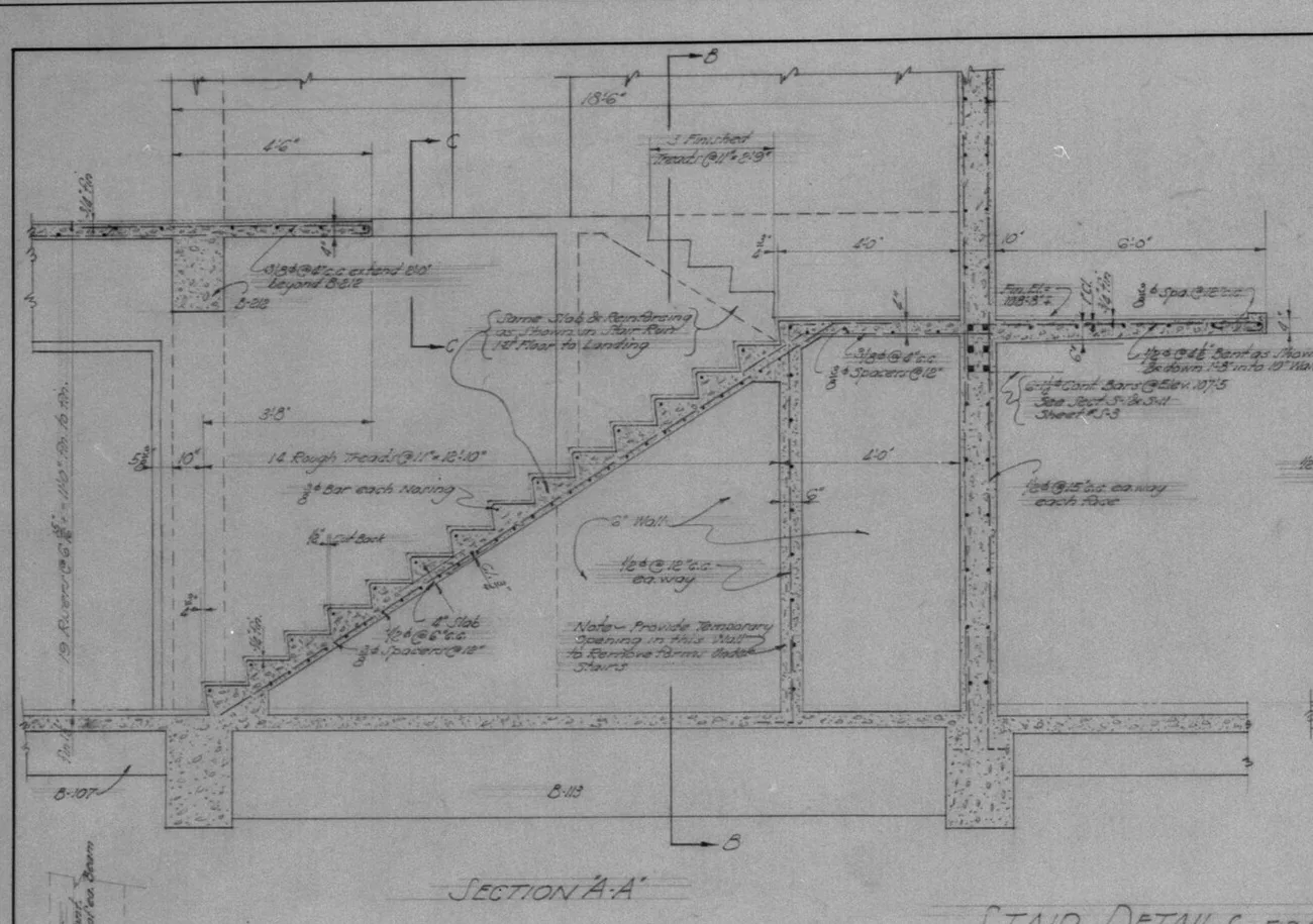
The section dimensions the flight as 19 risers at 6 15/16 inches, equal to 11 feet 0 inches finish to finish, and 14 rough treads at 11 inches, equal to 12 feet 10 inches. It draws a 4 inch waist slab with 1/2 inch bars at 6 inches on centre, and a 3/8 inch bar at each nosing to reinforce the step corners. The general notes base the design on concrete with an ultimate crushing strength of 2,000 pounds per square inch at 28 days.
One note on the drawing tells you more about concrete stairs than any textbook: it asks the builder to provide a temporary opening in the 6 inch wall to remove the forms under the stairs. A concrete section is also a construction sequence. If the formwork cannot get out, the stair cannot be built as drawn.
⚠️ Common Mistake to Avoid
Setting out risers from the structural slab instead of the finished floor. The 1941 Santa Barbara section avoids this by dimensioning the risers finish to finish and calling the concrete steps rough treads. If the floor finish at the top is thicker than at the bottom, a section drawn from the slabs gives a first or last riser that differs from the rest, which is exactly where people trip.
Steel Stair Section
Steel stairs are detailed around their connections. The sheet below is a section through a steel pan stair, drawn at 1/2 inch to 1 foot by @candicekaydesigns for a Detailing 2 assignment in the architectural program at St. Clair College in Windsor, Ontario, posted in 2018.

The labels read like a parts list for the type: C10x23 steel channel stringers with a steel closure, 12 gauge metal pan treads and risers, concrete topping in the pans with reinforcing mesh, small steel angles as tread supports and a 1 inch nosing. The guard has a 2 inch diameter top rail with 1/2 inch square pickets at 4 inches on centre, and the wall-mounted handrail is noted to extend 1 foot 0 inches beyond the top of the stair. The section also carries the whole stairwell, from the footing and weep tile to the roof parapet, so the stair is checked against the building around it.
The caption on the post makes the point every detailing course tries to teach: these are the drawings that matter, and you have to understand how things are constructed before you can draw them.
Timber Stair Section
In timber stairs the joints and small gaps carry the design. The construction drawing below is by Steven Baczek Architect, a residential practice in Reading, Massachusetts, and shows an open-riser stair between the first and second floor subfloors.
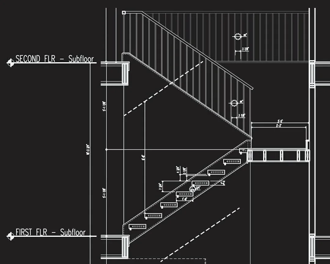
Open risers look simple, but the gap between treads has to satisfy the 4 inch sphere rule that Baczek refers to in his post. His drawing solves it with a cleat at each open riser that closes the gap down. He also laid out the top of the flight with a half tread at the landing, so the last step keeps an open riser instead of using the landing edge as a solid riser. That decision is invisible on a plan and only appears in section.
Real Stair Section Examples
The Historic American Buildings Survey, established in 1933, records buildings in measured drawings that are in the public domain, which makes it one of the best free libraries of stair sections anywhere. The two HABS sheets below take opposite approaches, and an eighteenth-century drawing shows how the stair drawing started as a presentation piece.
Fenwick Hall – Johns Island, South Carolina, USA
Survey: HABS SC-646 | Award: 2013 Charles E. Peterson Prize, second place

Fenwick Hall is a Georgian brick plantation house that HABS dates to about 1750, and that Wikipedia’s entry traces to a central block built by John Fenwick around 1730. The sheet, drawn by a student team with 31 named delineators, puts four related drawings side by side: a stair section through the whole house at 1/4 inch to 1 foot (1:48), a stair and rail detail at 3/4 inch to 1 foot (1:16), a stringer detail at 6 inches to 1 foot (1:2), and a newel post detail.
The sheet is a lesson in choosing scale. The 1:48 section explains how the stair rises through the house; the 1:16 detail carries the 11 1/4 inch tread and the balustrade dimensions; the 1:2 stringer detail is the only drawing large enough to show the carved scroll brackets on the open string. Its weakness for a builder is the same as its strength for a historian: it records what is there, with almost no information about how the timber is joined behind the finish.
Farnsworth House (1951) – Plano, Illinois, USA
Architect: Ludwig Mies van der Rohe | Detail scale: 1 inch to 1 foot (1:12)
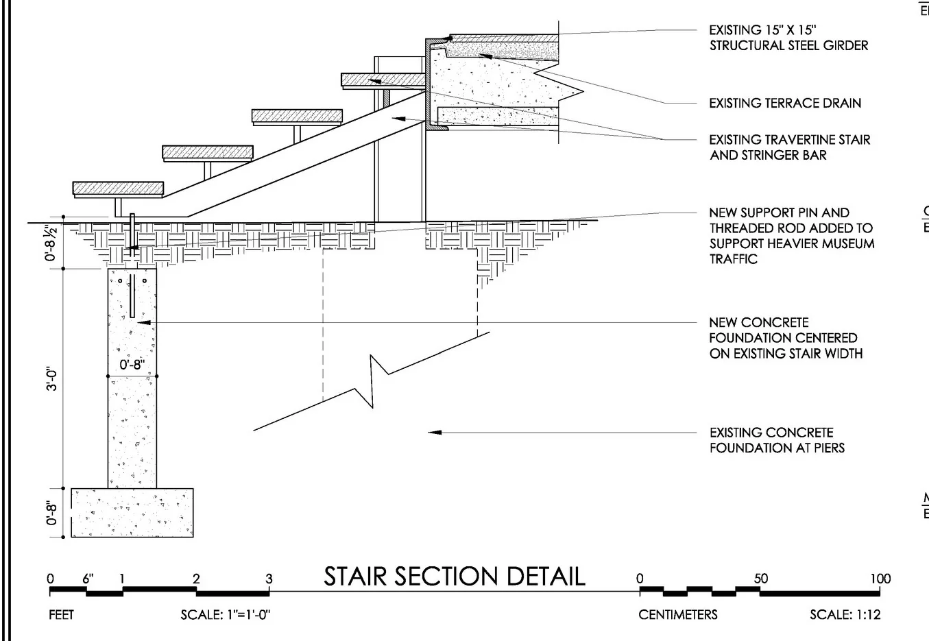
The travertine stairs of Mies van der Rohe’s Farnsworth House are among the most photographed steps in modern architecture, and this 2009 HABS stair section detail, drawn by Jenna Cellini, Elizabeth Milnarik and Brad Roeder, shows how little is holding them. Each travertine tread sits on a short post off a steel stringer bar, which rises to the steel girder at the edge of the terrace. The detail labels a 15 by 15 inch structural steel girder, the existing terrace drain and the existing concrete foundation at the piers.
The drawing also records a repair. It notes a new support pin and threaded rod added to support heavier museum traffic, and a new concrete foundation centred on the stair width, dimensioned 3 feet 0 inches deep on an 8 inch footing. The stair that looked like it floated needed a hidden footing once crowds replaced a single owner. The house itself is raised 5 1/4 feet above the Fox River floodplain and has still flooded, in the late 1990s and again in 2008, according to its Wikipedia entry.
Headfort House Staircase (1771 to 1775) – Kells, Ireland
Robert Adam designed the interiors of Headfort House in County Meath, and his section of one side of the staircase, now in the Yale Center for British Art, shows the stair as a profile of steps and a decorative balustrade set against a fully rendered wall of plaster panels, doors and an urn niche. It is a section in name, but its job was to sell the interior to the client. There is no structure, no level and no dimension beyond a scale bar, which is the clearest contrast with the 1941 Santa Barbara sheet.
📌 Did You Know?
Before CAD, stair builders learned their geometry from trade manuals. Fred T. Hodgson’s Common-Sense Stair Building and Handrailing, published in Chicago in 1903, projects curved handrail pieces from a plan and an inclined pitch line marked with the riser and the landing, the same lines you still draw in a staircase section today.
Common Mistakes in a Staircase Section Drawing
Cutting in the Wrong Place
A section line placed through the stairwell wall or the gap between flights produces a drawing with no cut treads. Cut through the flight itself, and say on the plan which way you are looking.
Counting Treads Instead of Risers
The total rise divides into risers, not treads. Drawing 15 treads for a 15 riser flight pushes the top step one going too far and makes the flight too long for its opening.
Skipping the Headroom Check
Headroom problems appear where the flight passes under the floor above. Draw the headroom line before you detail, not after, because fixing it usually means moving a beam or enlarging the stair opening.
Drawing a Stair That Hangs from Nothing
Every section should show the top and bottom connections. The Farnsworth detail is a reminder that even a celebrated stair can turn out to need a new footing when its load changes.
One Scale for Everything
A 1:50 section cannot carry a nosing profile, and a 1:5 detail cannot explain headroom. Fenwick Hall uses four scales on one sheet for this reason. Our guide to architectural drawing scales explains which scale fits which job.
💡 Pro Tip
When you are choosing a stair type early in design, sketch a quick section at 1:50 for each option before committing. A straight flight, an L-shaped stair and a winder can have the same plan footprint but very different headroom conflicts. Our stair design guide covers the types themselves.
Building codes and stair regulations vary by jurisdiction. Always confirm dimensions with the code that applies to your project and have structural details checked by a licensed professional.
Frequently Asked Questions
What is the difference between a stair section and a stair detail?
A stair section cuts through the whole flight to show levels, risers, treads, landings and headroom. A stair detail enlarges one part of it, such as a nosing, a stringer connection or a handrail fixing, at a much larger scale. Fenwick Hall’s HABS sheet shows both, with the section at 1:48 and the stringer detail at 1:2.
What scale should a stair section be drawn at?
There is no single scale; it depends on what the drawing has to explain. The examples here range from 1/4 inch to 1 foot (1:48) for the Fenwick Hall section, through 1/2 inch to 1 foot for the St. Clair College steel stair, to 1 inch to 1 foot (1:12) for the Farnsworth House detail that shows the support pin and foundation.
How do I work out the number of risers?
Divide the finished floor-to-floor height by your target riser height, round to a whole number, then divide again to get the exact riser. A 2850 mm rise with 190 mm risers gives 15 risers. Check the result against the riser limits in your local code before drawing.
What is a staircase section drawing used for on site?
Builders use it to set out the stair opening, check levels and headroom, order stringers or formwork, and place reinforcement and fixings. The 1941 Santa Barbara section even tells the contractor how to get the formwork out from under the stair.
Where to Go From Here
Your Next Step: Take a stair in a building you know, measure its total rise and one riser, and draw a 1:20 section of a single flight with the headroom line included. Once that one drawing closes, every riser count, landing and soffit on a larger project becomes a check you can do in minutes.













Leave a comment