


Table of Contents Show
To read architectural drawings, start with the title block and drawing index, then work through the three core views: plans show a building from above, sections cut through it vertically, and elevations show its exterior faces. Match every symbol to the legend and check the scale before you measure anything.
A full set of drawings can feel like a wall of lines and abbreviations the first time you open one. The good news is that architectural drawings follow a consistent visual language. Once you understand what each drawing type represents and how the sheets connect, the whole set starts to make sense. This guide walks through plans, sections, and elevations, then covers the scale, symbols, and cross-references that tie them together.
What Are Plans, Sections, and Elevations?
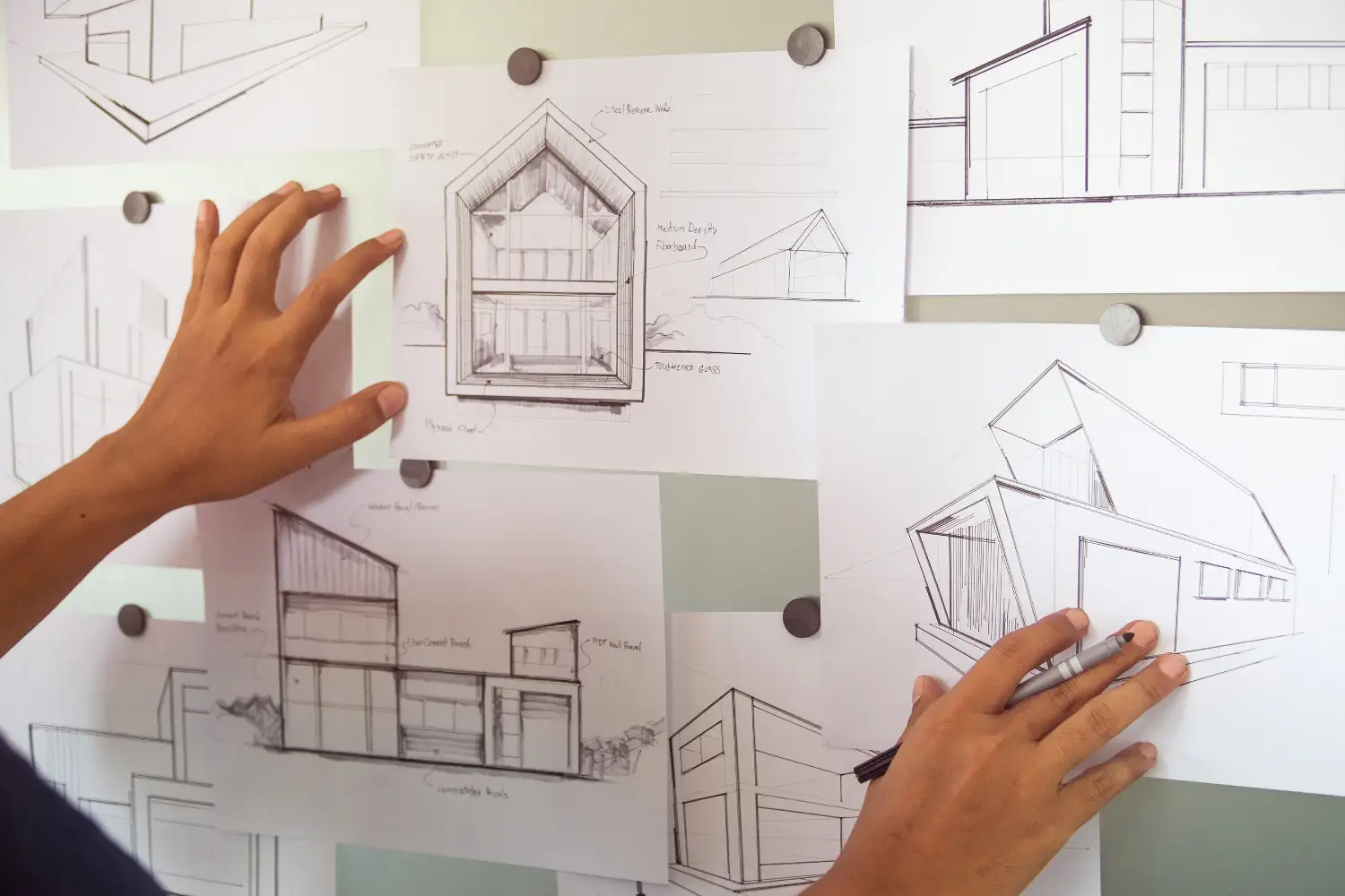
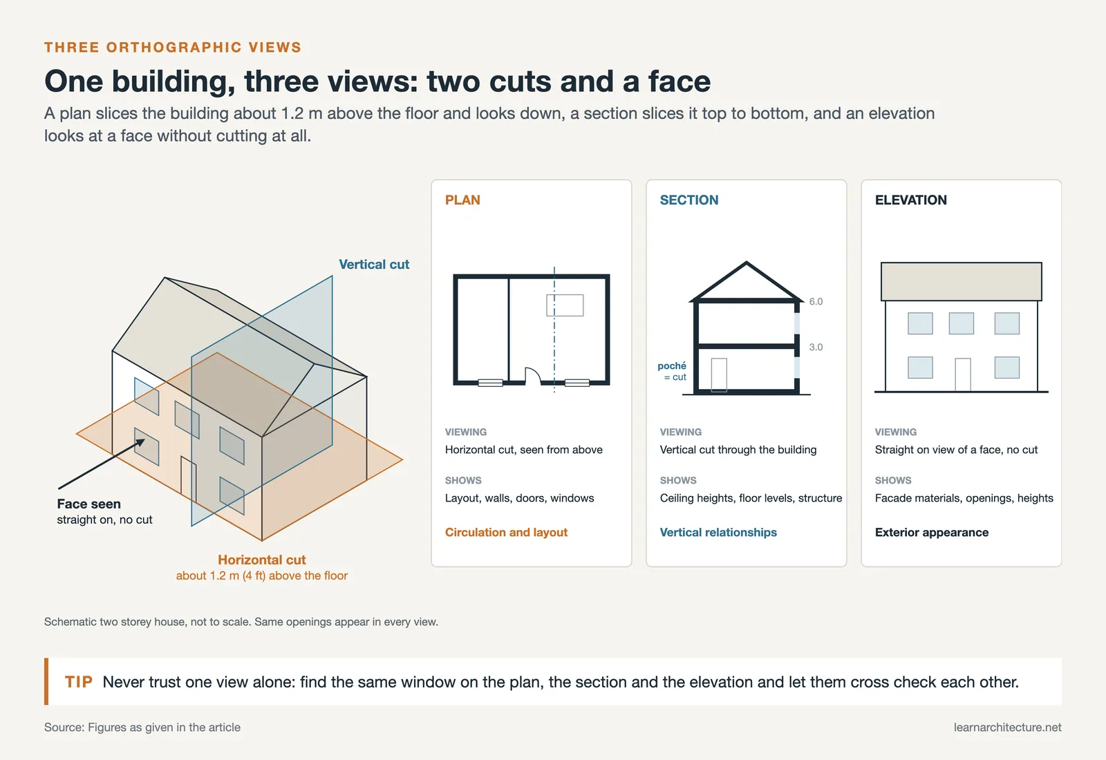
Architectural drawings are two-dimensional representations of a three-dimensional building, drawn using orthographic projection so nothing is distorted by perspective. A plan is a horizontal slice viewed from above. A section is a vertical slice that reveals what sits inside the building. An elevation is a straight-on view of an exterior face, with no cut at all.
Each view answers a different question. Plans handle layout and circulation, sections explain height and structure, and elevations describe how the building meets the street. You rarely rely on one drawing alone. Reading a design well means moving between all three and letting them cross-check each other. Drawings are also one part of a wider family of representation tools, from architectural diagrams to 3D views.
📌 Did You Know?
The word “blueprint” comes from an old reproduction method called cyanotype, which printed white lines on a deep blue background. Modern construction sets are printed in full color or black and white, but the nickname stuck, so people still call any drawing set a set of blueprints.
Plans vs Sections vs Elevations: What Each One Shows
The table below sums up how the three drawing types differ:
| Drawing Type | Viewing Direction | What It Shows | Best For |
|---|---|---|---|
| Plan | Horizontal cut, seen from above | Room layout, walls, doors, windows | Circulation and spatial arrangement |
| Section | Vertical cut through the building | Ceiling heights, floor levels, structure | Understanding vertical relationships |
| Elevation | Straight-on view of a face, no cut | Facade materials, openings, proportions | Exterior appearance and heights |
How to Read a Floor Plan
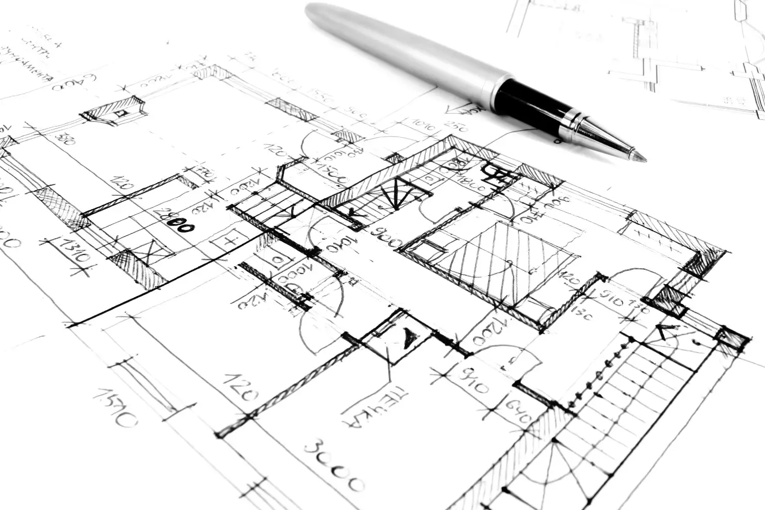
A floor plan shows the building as if you sliced it horizontally, usually about 1.2 meters (4 feet) above the floor, and looked straight down. Everything the cut passes through, mainly walls, appears as a solid cut, while items below the cut line, such as furniture, show up as lighter outlines.
Read walls by their thickness first. Thicker cuts usually mean structural or exterior walls, and thinner ones mean interior partitions. Doors appear as a gap with a quarter-circle arc showing the swing direction, and windows read as thin parallel lines set into the wall. Stairs use direction arrows and a break line. For a full breakdown of these conventions, our guide to architectural symbols works as a companion to this one.
💡 Pro Tip
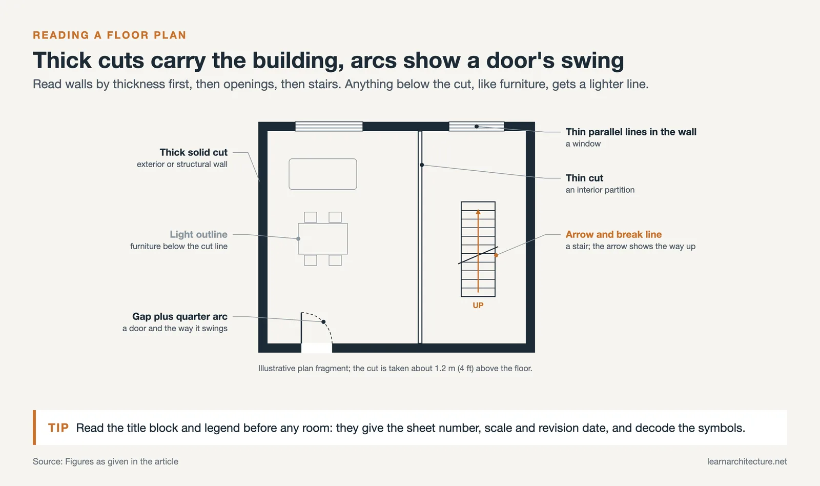
Before you interpret a single room, read the title block and the legend on each sheet. The title block gives you the sheet number, scale, and revision date, and the legend decodes the symbols used across the set. Skipping this step is the fastest way to misread a drawing.

How to Read a Section Drawing
A section drawing, sometimes called an architecture section drawing, cuts vertically through the building, as if you sliced it top to bottom and looked at the exposed face. Sections are where vertical information lives: ceiling heights, floor-to-floor dimensions, roof pitch, foundations, and how one level stacks on the next.
The heaviest linework, often filled in solid using a technique called poché, marks whatever the cut passes through, such as walls, slabs, and beams. Lighter lines show what sits beyond the cut in the background. This contrast is what lets you separate the structure from the space. Our detailed look at reading section drawings goes deeper into full, half, and detail sections.
📐 Technical Note
Under ISO 128-23, construction drawings use a defined set of line types and thicknesses, with heavy lines reserved for the cut and lighter lines for elements beyond it. This is why lineweight, not color, is usually the first thing to read on a section.
How to Read an Elevation Drawing
An elevation is a flat, straight-on view of a single face of the building, drawn without any cut through it. Where a section reveals the inside, an architectural drawing elevation shows the outside: window and door placement, material changes, rooflines, and how tall each part of the facade is. For a practicing architect’s walkthrough of these three views, Fontan Architecture’s plan, section, and elevation explainer is a useful reference.
Depth on an elevation comes through lineweight rather than perspective. Elements closest to you are drawn with the darkest, heaviest lines, and features that sit further back fade to lighter lines. Level markers along the side tie the elevation back to the heights shown in the section, which is one more reason to read the two together. If you want to see how plan, section, and elevation combine into a single 3D image, our isometric drawing tutorial connects them.

Scale, Symbols, and Cross-References
Three things apply to every sheet in the set, whatever the drawing type. The first is scale. Residential plans are commonly drawn at 1:50 or 1:100, or a quarter inch to a foot in imperial, and every dimension you read depends on knowing that ratio. The second is symbols, a shared shorthand for doors, fixtures, grid lines, and materials. The third is cross-referencing.
Cross-references act as the map of a drawing set. A bubble on a plan might point you to a section on sheet A302, which in turn references a detail on sheet A702. Following those callouts, rather than reading each sheet in isolation, is how you trace the logic of the whole building. This habit is what separates skimming a drawing from actually reading architectural drawings.
⚠️ Common Mistake to Avoid
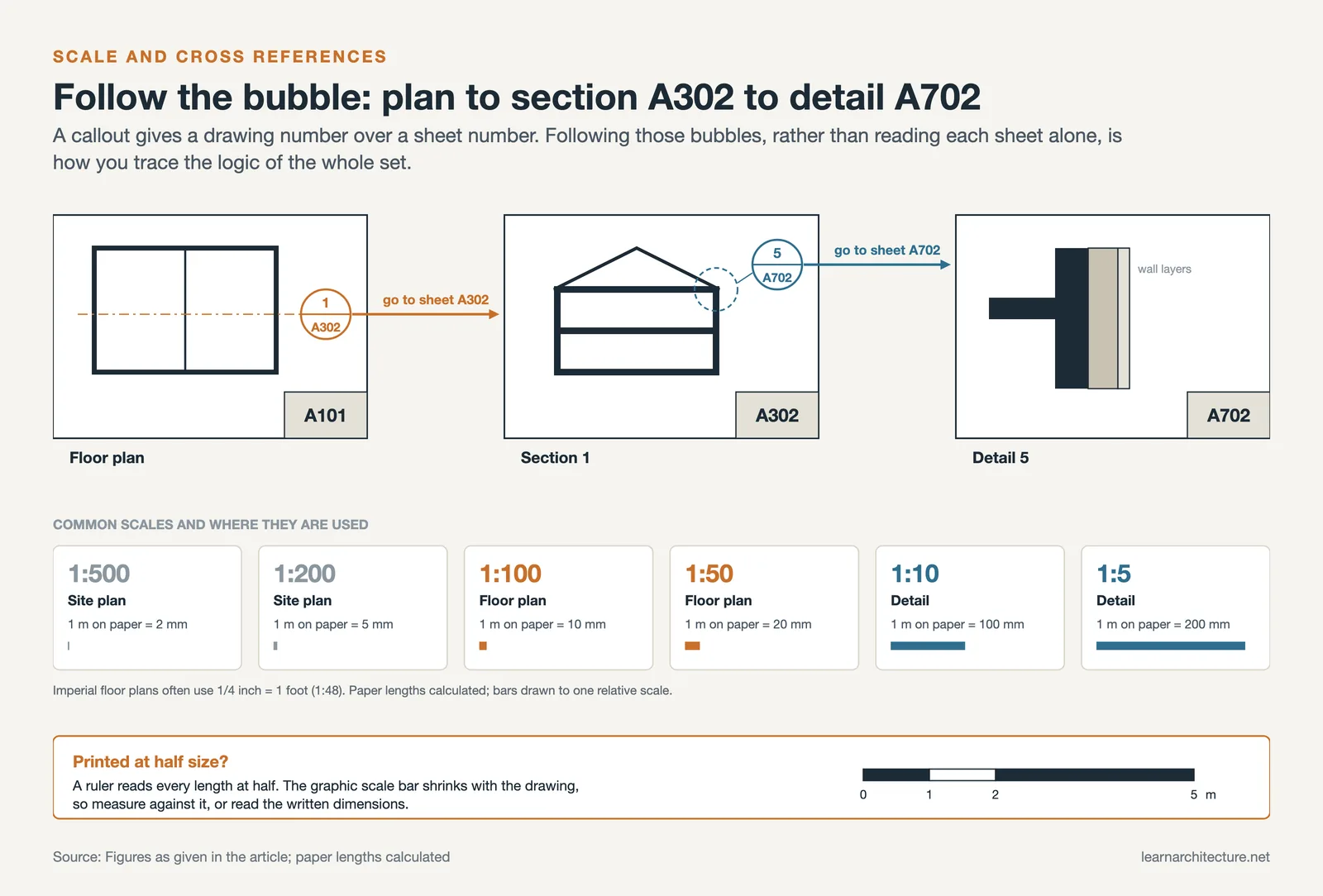
A frequent error is measuring straight off a printed sheet with a ruler. Drawings are only accurate at their stated scale, and a set printed at half size or shrunk to fit a PDF will give you the wrong numbers. Always read the written dimensions, or use the graphic scale bar, which shrinks and grows along with the drawing.
Where to Go From Here
Your Next Step: Find a real drawing set, even a simple house plan from an online archive or your local building department, and practice moving from the plan to the matching section and elevation for the same room. Reading across the three views on an actual project is what turns these conventions into second nature. If you want to start drawing them yourself, our step-by-step guide to drawing a floor plan is a good place to begin.

Frequently Asked Questions
What is the difference between a section and an elevation?
A section cuts through the building and shows what is inside, including structure and ceiling heights. An elevation shows an exterior face from straight on, with no cut. In short, a section reveals the interior, while an elevation describes the outside.
In what order should you read a set of architectural drawings?
Start with the title block and drawing index to see how the set is organized. Read the site plan and floor plans for layout, then move to sections and elevations for height and appearance. Finish with the details, following the cross-reference callouts as you go.
What scale are architectural drawings usually drawn at?
Residential floor plans are commonly drawn at 1:50 or 1:100 in metric, or a quarter inch to one foot in imperial. Site plans use smaller scales such as 1:200 or 1:500, and construction details use larger scales like 1:5 or 1:10 to show how parts fit together up close.
Do you need to be an architect to read architectural drawings?
No. Homeowners, builders, students, and clients all read drawings regularly, and you do not need to draft them to understand them. Learning the core symbols, the three main drawing types, and how scale works is enough to follow most residential and small commercial sets.










Leave a comment